92 D90
PLUS
LINE DISTANCE PROTECTION SYSTEM – INSTRUCTION MANUAL
COMMUNICATIONS OVERVIEW CHAPTER 6: COMMUNICATIONS
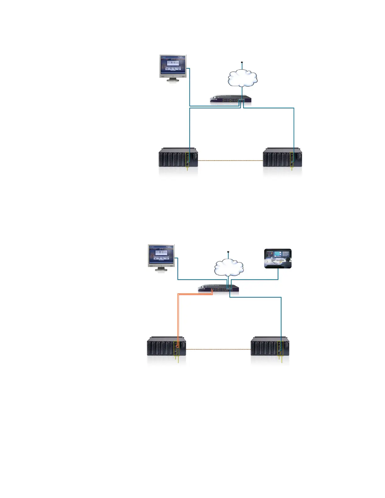
Figure 70: Simple network topology without communications cards
The topology shown as follows allows SCADA, GOOSE, configuration, and monitoring
functions to share a single network. No redundancy is provided. A communications
processor is required in each D90
Plus
device to facilitate SCADA and GOOSE messaging.
Ports 2 and 3 can be configured for single or dual IP redundancy. This network topology is
backwards-compatible with UR-series devices that are configured with a single Ethernet
port.
Figure 71: Simple single network topology with no redundancy
The following topology illustrates a single network for SCADA, GOOSE, configuration, and
monitoring functions. This configuration provides redundant hardware and media
redundancy. All communications are handled by port 2 under normal circumstances.
Failure of a fiber or Ethernet switch causes the communications to be re-routed to port 3.
Ports 2 and 3 are configured for single IP redundancy in this case. This network topology is
backwardly compatible with UR-series devices that are configured with dual Ethernet
ports.
$&'5
3XEOLFQHWZRUN
*DWHZD\
/$1
0XOWL/LQN0/VZLWFK
85 VHULHV,('
3OXV
85 VHULHV,('
3OXV
(QHU9LVWD
VRIWZDUH
&38
&38
$&'5
3XEOLFQHWZRUN
*DWHZD\
/$16&$'$DQG*226(
0XOWL/LQN0/VZLWFK
85 VHULHV,('
3OXV
85 VHULHV,('
3OXV
(QHU9LVWD
VRIWZDUH
&38
&38
&RPPXQLFDWLRQV &RPPXQLFDWLRQV
6&$'$