46 D90
PLUS
LINE DISTANCE PROTECTION SYSTEM – INSTRUCTION MANUAL
WIRING CHAPTER 3: INSTALLATION
IRIG-B port
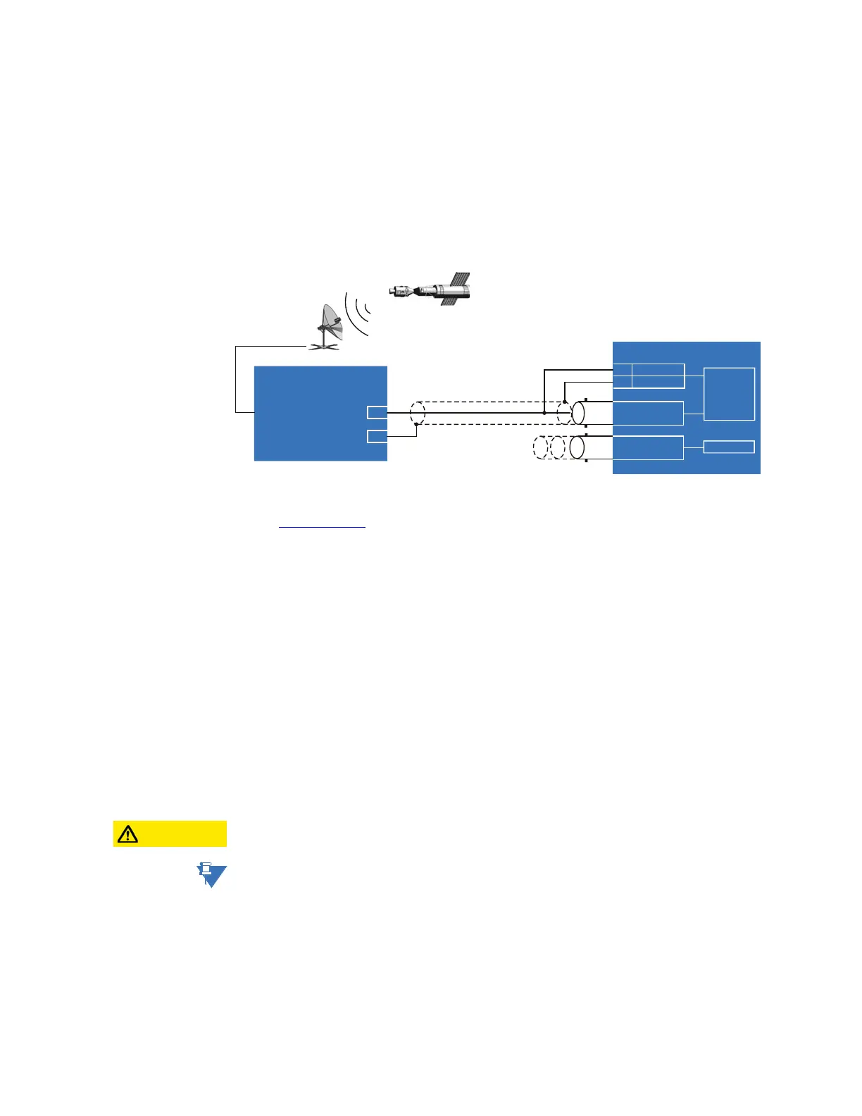
IRIG-B is a standard time code format that allows stamping of events to be synchronized
among connected devices. The IRIG-B code allows time accuracies of up to 100 ns. The
IRIG time code formats are serial, pulse width-modulated codes that can be either DC level
shifted or amplitude modulated (AM).
Third party equipment is available for generating the IRIG-B signal; this equipment can use
a global positioning system (GPS) satellite system to obtain the time reference so that
devices at different geographic locations can be synchronized.
Figure 21: IRIG-B connection
For additional information, refer to:
Real-time clock
on page 146
Communications module
The communications module in slot C contains two ports for Ethernet communications,
designated as port 2 and port 3. These are fully independent from each other and from
port 1 on the main processor module. The communications module ports support
redundancy and several protocols not supported by port 1.
The fiber optic ports allow for fast and efficient communication between devices at
100 Mbps. Optical fiber can be connected to the D90
Plus
supporting a wavelength of
1310 nm in multimode.
The optical fiber sizes supported are 50/125 µm and 62.5/125 µm. The fiber optic port is
designed such that the response time does not vary for any core that is 62.5 µm or less. For
optical power budgeting, splices are required every 1 km for the transmitter-receiver pair.
When splicing optical fibers, the diameter and numerical aperture of each fiber must be
the same. In order to engage or disengage the ST type connector, only a quarter turn of the
coupling is required.
CAUTION:
Observing any fiber transmitter output can injure the eye.
NOTE:
Ensure the dust covers are installed when the fiber is not in use. Dirty or scratched
connectors can lead to high losses on a fiber link.
Power supply module
The power supply module in slot A provides power to the relay and supplies power for dry
contact input connections. It can be connected to any of the following standard power
sources:
85
3OXV
VHULHVGHYLFH
%1&,1
5HFHLYHU
5*FRD[LDOFDEOH
*36VDWHOOLWHV\VWHP
*36FRQQHFWLRQ
RSWLRQDO
,5,*%²
$
²
$&'5
,5,*%
7,0(&2'(
*(1(5$725
'&VKLIWRU
DPSOLWXGHPRGXODWHG
VLJQDOFDQEHXVHG
%
,5,*%
5HSHDWHU
7RRWKHUGHYLFHV
'&VKLIWRQO\
%1&287