78 D90
PLUS
LINE DISTANCE PROTECTION SYSTEM – INSTRUCTION MANUAL
ANNUNCIATOR CHAPTER 4: FRONT PANEL INTERFACE
Self-test page
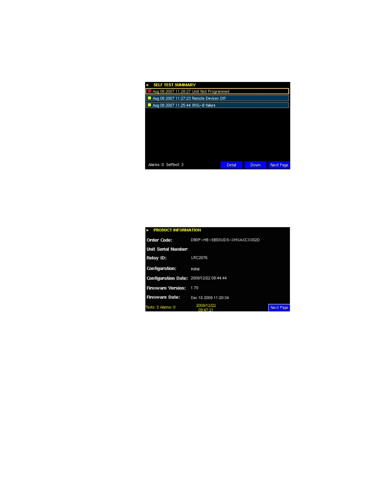
This page displays any active self-test alarms as well as the time of occurrence and the
severity of the alarm (yellow for non-critical and red for critical).
Figure 58: Self-test page example
Product information page
The product information page contains data describing the device, including the order
code, serial number, device identification name, setting configuration name, time of last
change, firmware version, and firmware release date.
Figure 59: Sample product information page
The Relay ID value reflects the string entered as the
Relay Name in the Settings >
Protection > Power System > Installation menu. The Configuration value reflects the
string entered as the
User Configuration Name in the Settings > Protection > Power
System > Installation menu. The setup program automatically updates the Configuration
Date after each setting change. The current D90
Plus
date and time display on all
annunciator pages, as does the total number of active self-tests and alarms.
Communication status page
This page outlines the available TCP/IP connections for the supported protocols and the IP
addresses of the ports used.
The D90
Plus
supports up to five Manufacturing Message Specification (MMS) connections,
four Modbus connections, two Distributed Network Protocol (DNP) connections, and one
Phasor Measurement Unit (PMU) connection. The DNP connections are shown as available
if the protocol has been enabled and the D90
Plus
restarted.