CHAPTER 3: INSTALLATION PANEL CUTOUTS
D90
PLUS
LINE DISTANCE PROTECTION SYSTEM – INSTRUCTION MANUAL 41
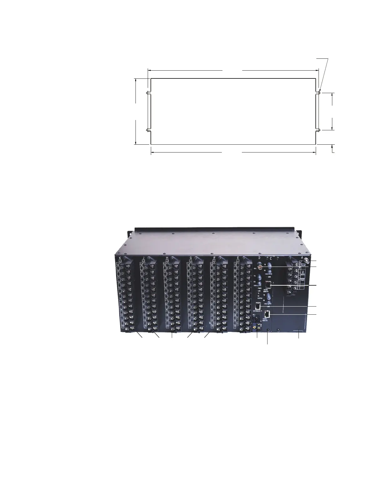
Figure 17: Panel cutout dimensions
Rear terminal layout
Terminal number assignments in the D90
Plus
are represented by three characters,
assigned in order by module slot position, row number, and column letter. The figure
provides an example of rear terminal assignments.
Figure 18: Rear terminal view
Slot A houses the power supply module.
Slot B houses the inter-relay communication module (not shown).
Slot C houses the communications module.
Slot D houses the main processing card.
870725A2.CDR
7.13"
(181.1 mm)
CUTOUT
17.75"
(450.8 mm)
18.37"
(466.6 mm)
1.57"
(39.8 mm)
4.00"
(101.6 mm)
4 × 0.28" diameter
(7.1 mm)
870824A3.CDR
Power supply module
Grounding post
Communications module
CPU moduleContact input/output modules
Ethernet Port 1
Ethernet Port 3
Ethernet Port 2
IRIG-B