448 D90
PLUS
LINE DISTANCE PROTECTION SYSTEM – INSTRUCTION MANUAL
AUTOMATION CONTROL CHAPTER 8: AUTOMATION
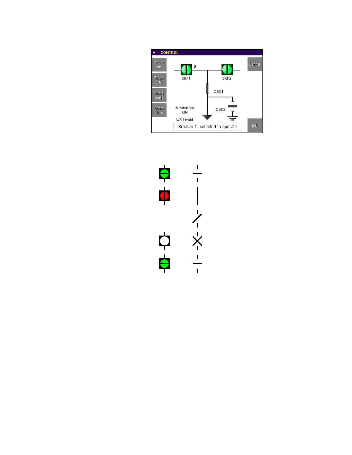
Figure 379: Breaker 1 status substituted
The following indications are provided for breakers and disconnects.
Figure 380: Front panel indicators for breakers and disconnects
Local-remote control scheme
The local-remote control scheme is used to define the current location for operator control
of power system devices (for example, breakers, disconnects). The function accepts inputs
from the front panel interface or from an external source. The automation logic outputs (L/
R-L On and L/R-R On) are assigned as inputs to the breaker and disconnect elements. The
position of the latch is stored in non-volatile memory.
Select the Settings > Automation > Control > Local-Remote menu to open the local-
remote control scheme configuration window.
$&'5
7
6
'HYLFHLVWDJJHG7
6WDWXVLVVXEVWLWXWHG6
2SHQHGLQGLFDWLRQ
&ORVHGLQGLFDWLRQ
,QWHUPHGLDWHLQGLFDWLRQ
%DGVWDWXV
7
6
%UHDNHUV
'LVFRQQHFWV
1RW
DSSOLFDEOH