44 D90
PLUS
LINE DISTANCE PROTECTION SYSTEM – INSTRUCTION MANUAL
WIRING CHAPTER 3: INSTALLATION
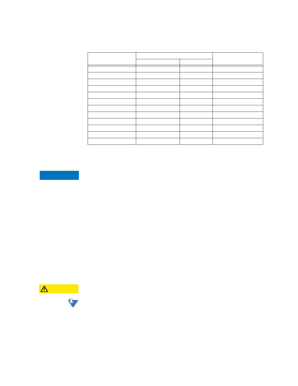
The table shows the dielectric strength of the UR
Plus
-series module hardware.
Table 1: Dielectric strength for UR
Plus
-series hardware
Filter networks and transient protection clamps are used in the hardware to prevent
damage caused by high peak voltage transients, radio frequency interference (RFI), and
electromagnetic interference (EMI).
FAST PATH:
The protective components can be damaged by application of any test voltage for a
period longer than the specified minute.
Main processor module
The main processor module in slot D contains ports for Ethernet communications, serial
RS485 communications, and IRIG-B connection.
Ethernet port
The fiber optic communication ports allow for fast and efficient communications between
relays at 100 Mbps. Optical fiber can be connected to the relay supporting a wavelength of
1310 nm in multi-mode.
The optical fiber sizes supported are 50/125 µm and 62.5/125 µm. The fiber optic port is
designed such that the response times do not vary for any core that is 62.5 µm or less in
diameter. For optical power budgeting, splices are required every 1 km for the transmitter-
receiver pair. When splicing optical fibers, the diameter and numerical aperture of each
fiber must be the same. In order to engage or disengage the ST type connector, only a
quarter turn of the coupling is required.
CAUTION:
Observing any fiber transmitter output can injure the eye.
NOTE:
Ensure the dust covers are installed when the fiber is not in use. Dirty or scratched
connectors can lead to high losses on a fiber link.
RS485 port
RS485 data transmission and reception are accomplished over a single twisted-pair wire
with transmit and receive data alternating over the same two wires. Through the use of
this port, continuous monitoring and control from a remote computer, SCADA system, or
Power Line Carrier (PLC) is possible.
Function Terminals Dielectric strength
from to
Power supply module high (+), low (+), (–) chassis 2000 V AC for 1 minute
Power supply module 48 V DC (+) and (–) chassis 2000 V AC for 1 minute
Power supply module relay terminals chassis 2000 V AC for 1 minute
Main CPU RS485 port chassis 2000 V AC for 1 minute
Main CPU RJ45 port chassis 1500 V AC for 1 minute
Main CPU IRIG-B port chassis 2000 V AC for 1 minute
Front panel USB port chassis 2000 V AC for 1 minute
Contact inputs/outputs all chassis 2000 V AC for 1 minute
AC module all chassis 2000 V AC for 1 minute
Communications module RS45 ports chassis 1500 V AC for 1 minute
G.703 module all except 1a, 8a chassis 1000 V AC for 1 minute
RS422 module all except 1a, 8a chassis 1500 V AC for 1 minute