CHAPTER 12: LOCAL INTERFACE MIMIC DIAGRAM EDITOR
D90
PLUS
LINE DISTANCE PROTECTION SYSTEM – INSTRUCTION MANUAL 591
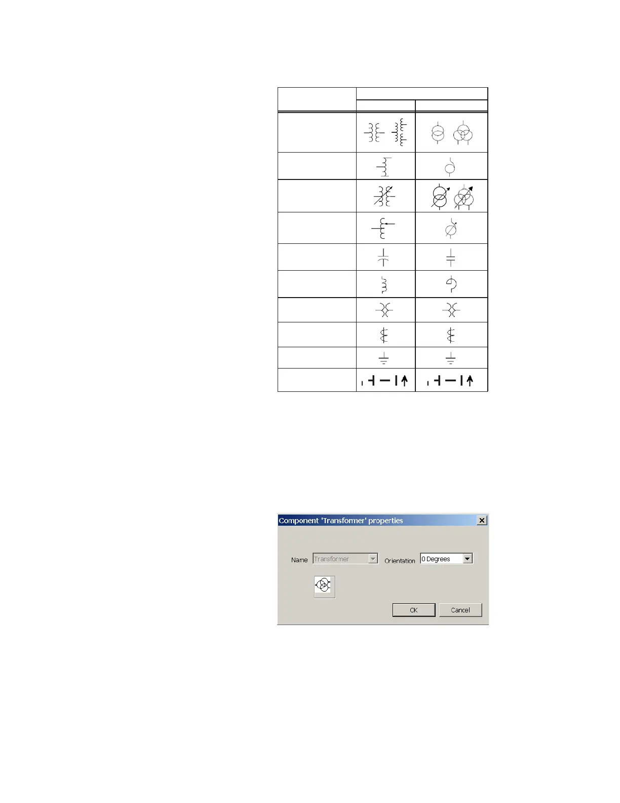
Figure 518: Mimic diagram editor static symbols
For more information on these symbols, see the ANSI/IEEE 315A and IEC 617 standards.
There is no limit on the number of static symbols per screen, provided that they fit within
the screen dimensions.
When a static symbol is selected and added to the diagram, a window appears to
configure the device. This allows the user to specify the orientation of the device; the name
of a static device cannot be changed. The figure shows the transformer properties device
configuration window.
Figure 519: Transformer properties device configuration window
Metering blocks
Metering blocks can display various metered quantities. They allow the user to display
specific analog values in the mimic diagram. The table outlines the metered text block
type. A maximum of six metering blocks can be used per mimic diagram page.
6\PEROV&RPSRQHQWV
6WDQGDUG ,(&
7UDQVIRUPHU
$XWRWUDQVIRUPHU
7UDQVIRUPHU ZLWK
WDSFKDQJHU
$&'5
$XWRWUDQVIRUPHU ZLWK
WDSFKDQJHU
&DSDFLWRU EDQN
5HDFWRU
97
&7
*URXQGLQJ
%XVEDU DQG
WUDQVPLVVLRQOLQHV