CHAPTER 15: THEORY OF OPERATION SINGLE-POLE TRIPPING
D90
PLUS
LINE DISTANCE PROTECTION SYSTEM – INSTRUCTION MANUAL 665
used). The permissive echo is programmed as a one-shot logic. The echo is sent only once
and then the echo logic locks out for a user-specified period. The duration of the echo
pulse does not depend on the duration or shape of the received RX signal but is
programmable with the
Echo Duration setting. The echo is sent back only if none of the
overreaching protection elements operates.
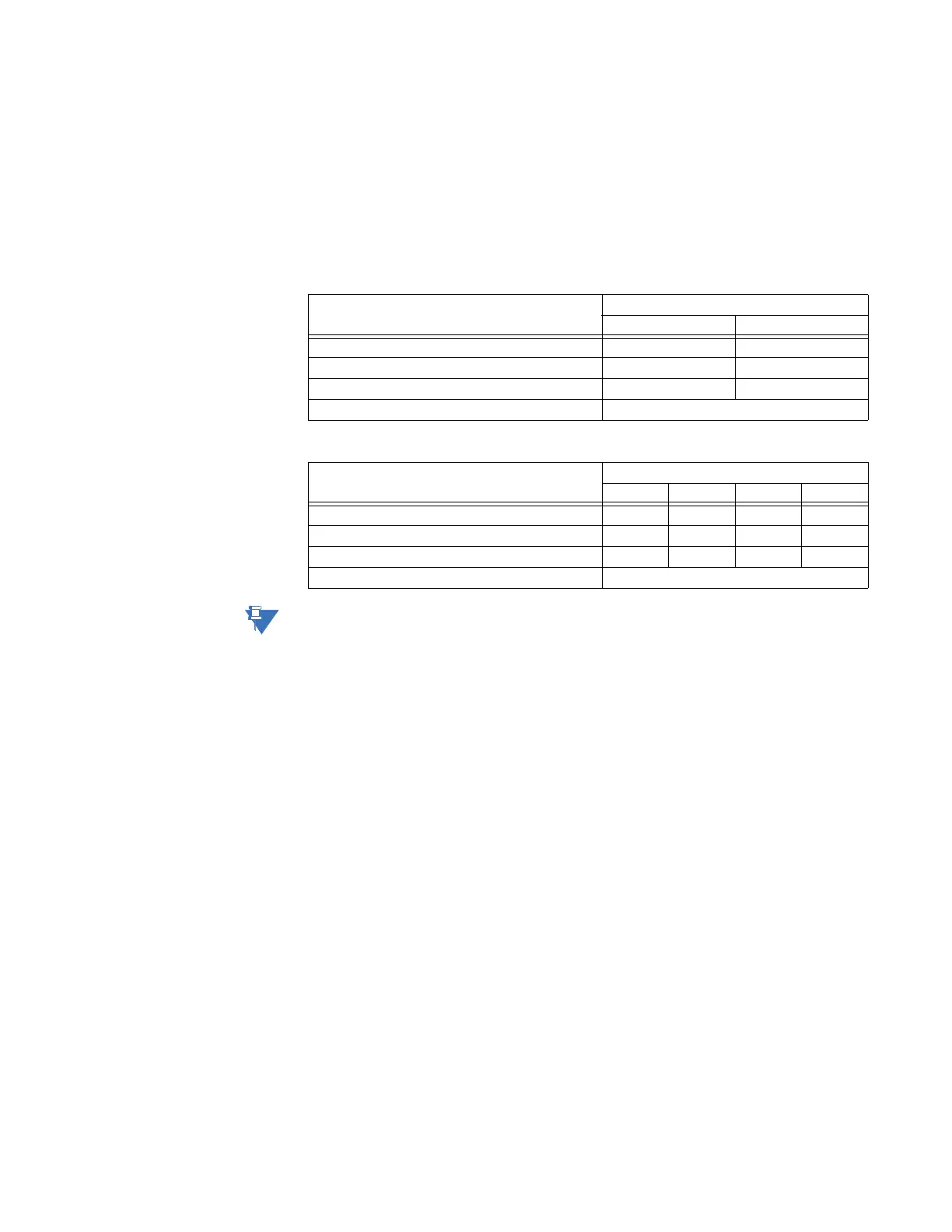
In single-pole tripping, single-bit channel applications the signal received on bit 1 (RX1) is
echoed back on bit 1 (TX1). In two-bit and four-bit applications, the following echo tables
apply for operands and transit codes.
Table 46: Echo table for two-bit channels
Table 47: Echo table for four-bit channels
NOTE:
For the directional comparison unblocking scheme, the echo is performed in the same
manner as the hybrid POTT echo, but by additionally applying the following logic for both
the Rx (received) and LOG (loss-of-guard) for each channel: ECHO = LOG AND Rx.
Pilot scheme and phase selector coordination
The pilot schemes use the phase selector for local fault type identification. The latter can
fail to respond to certain fault scenarios. Examples include simultaneous forward and
reverse fault, simultaneous SLG and LL fault involving different phases (for example, AG
and BC) or two simultaneous faults in the same direction but at very different locations.
The phase selector is optimized to indicate correctly the forward fault or to assert the VOID
flag. For example, a combination of AG and BC is not a valid fault type. Rather, it is two
different, simultaneous faults and as such cannot be described by any single fault pattern.
Therefore, the phase selector asserts the VOID flag.
The VOID phase selection combined with a local trip request (such as high-set directional
overcurrent) results in three-pole trip as per the trip output logic.
The pilot schemes, however, try to recover additional information from the distance
elements. Each scheme uses a forward-looking (either underreaching or overreaching)
distance zone. A given pilot scheme analyzes this zone for fault type identification if the
phase selector asserts its VOID flag. The DUTT scheme uses zone 1, while all other schemes
use zone 2. The schemes analyze all six fault loops of the zone to determine the fault type.
For example, simultaneous forward AG and reverse BG faults can result in the VOID
indication. The POTT scheme analyzes the zone 2 response. As only the AG element is
picked up, the local phase selection is determined as AG. This is a correct indication.
Depending on the number of bits used for communications, the accuracy of the overall
response is further improved as illustrated in the next section.
Local determination of fault type Echoed bits
TX1 TX2
AG 1 0
BG 0 1
CG 1 1
AB, ABG, BC, BCG, CA, CAG, 3P, or unrecognized sent back as received
Local determination of fault type Echoed bits
TX1TX2TX3TX4
AG 1 0 0 0
BG 0 1 0 0
CG 0 0 1 0
AB, ABG, BC, BCG, CA, CAG, 3P, or unrecognized sent back as received