8D90
PLUS
LINE DISTANCE PROTECTION SYSTEM – INSTRUCTION MANUAL
PRODUCT DESCRIPTION CHAPTER 2: PRODUCT DESCRIPTION
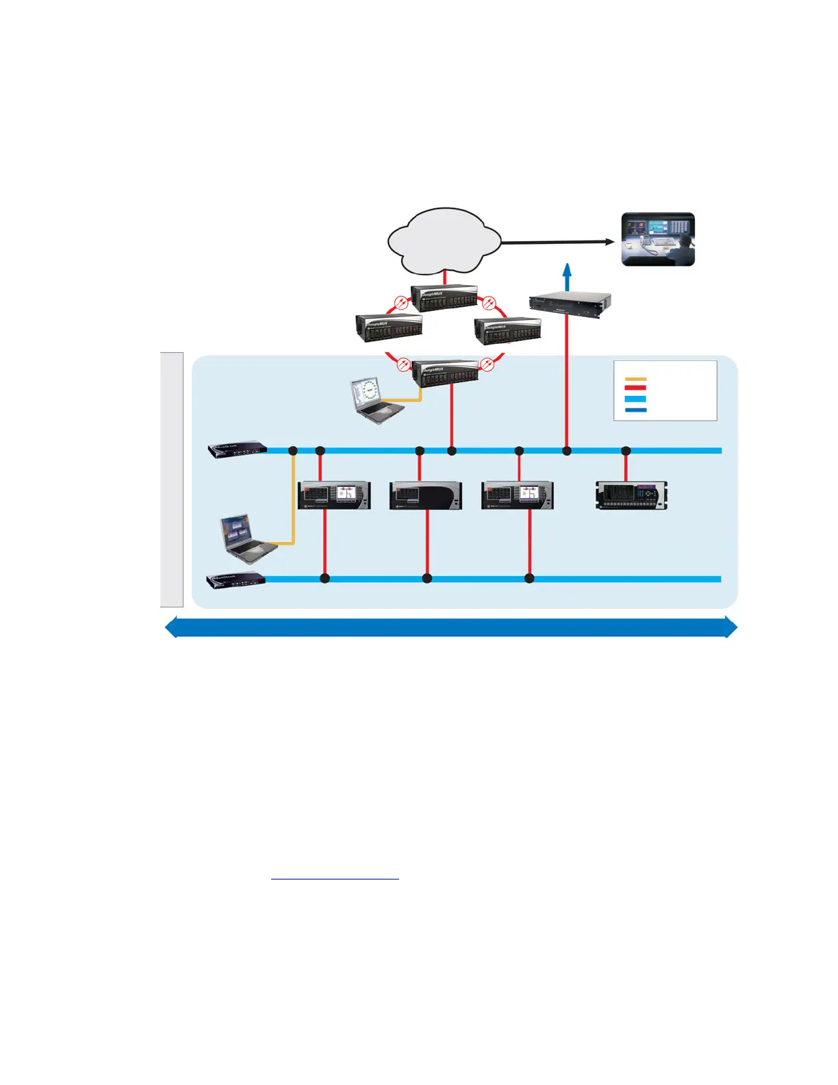
Communications overview
The EnerVista UR
Plus
Setup software can communicate with the relay through three ports:
the front panel USB port, the rear Ethernet port, and the rear RS485 port. Both rear ports
are located in slot D.
Figure 4: Communications overview
To communicate through the D90
Plus
rear RS485 port from a computer’s RS232 port, the
GE Multilin RS232/RS485 converter box is required. This device (catalog number F485)
connects to the computer using a straight-through serial cable. A shielded twisted-pair (20,
22, or 24 AWG) connects the F485 converter to the D90
Plus
rear communications port. The
converter terminals (+, –, GND) are connected to the D90
Plus
communication module (+, –,
COM) terminals. Terminate the line with a 120 Ω, 1 nF R-C network.
Communications via Ethernet requires a connection to an Ethernet network using a
standard copper or fiber cable. The Ethernet port can also connect directly to a computer
using a cross-over cable.
To communicate via the faceplate USB port, use a standard USB serial cable. No converter
box is required.
For additional information, refer to:
Main processor module
on page 44.
Front panel interface
Information is displayed on the D90
Plus
front panel through two display panels. One serves
as a digital annunciator and the other reflects display and control functions. The panels
provide easy access and visualization of device information, ranging from the large display
$&'5
853OXV
VHULHV,('
853OXV
VHULHV,('
853OXV
VHULHV,('
2WKHU,(&,('V
,(&
VXEVWDWLRQFRQILJXUDWLRQ
(QHU9LVWDVRIWZDUH
0XOWL/LQN
(WKHUQHWVZLWFKHV
9LVWD1(7VRIWZDUH
&25325$7(
:$1
2WKHUVXEVWDWLRQV
6XEVWDWLRQ&
6XEVWDWLRQ%
-XQJOH08;718
8QLYHUVDOPXOWLSOH[HU
6XEVWDWLRQ$
(06
'06
6&$'$
6\VWHPFRQWUROFHQWHU
5HJLRQDOFRQWUROFHQWHU
(QJLQHHULQJ
3ODQQLQJ
+LVWRULDQ
6XEVWDWLRQJDWHZD\
DOWHUQDWLYH
6&$'$
/(*(1'
&RSSHU
)LEHU
+XEVZLWFK
6&$'$
FRPPXQLFDWLRQV
(WKHUQHW
5HGXQGDQWQHWZRUN
23(135272&2/²,(&
&203/,$17,('V
68%67$7,21$