400 D90
PLUS
LINE DISTANCE PROTECTION SYSTEM – INSTRUCTION MANUAL
PROTECTION INPUTS AND OUTPUTS CHAPTER 7: PROTECTION
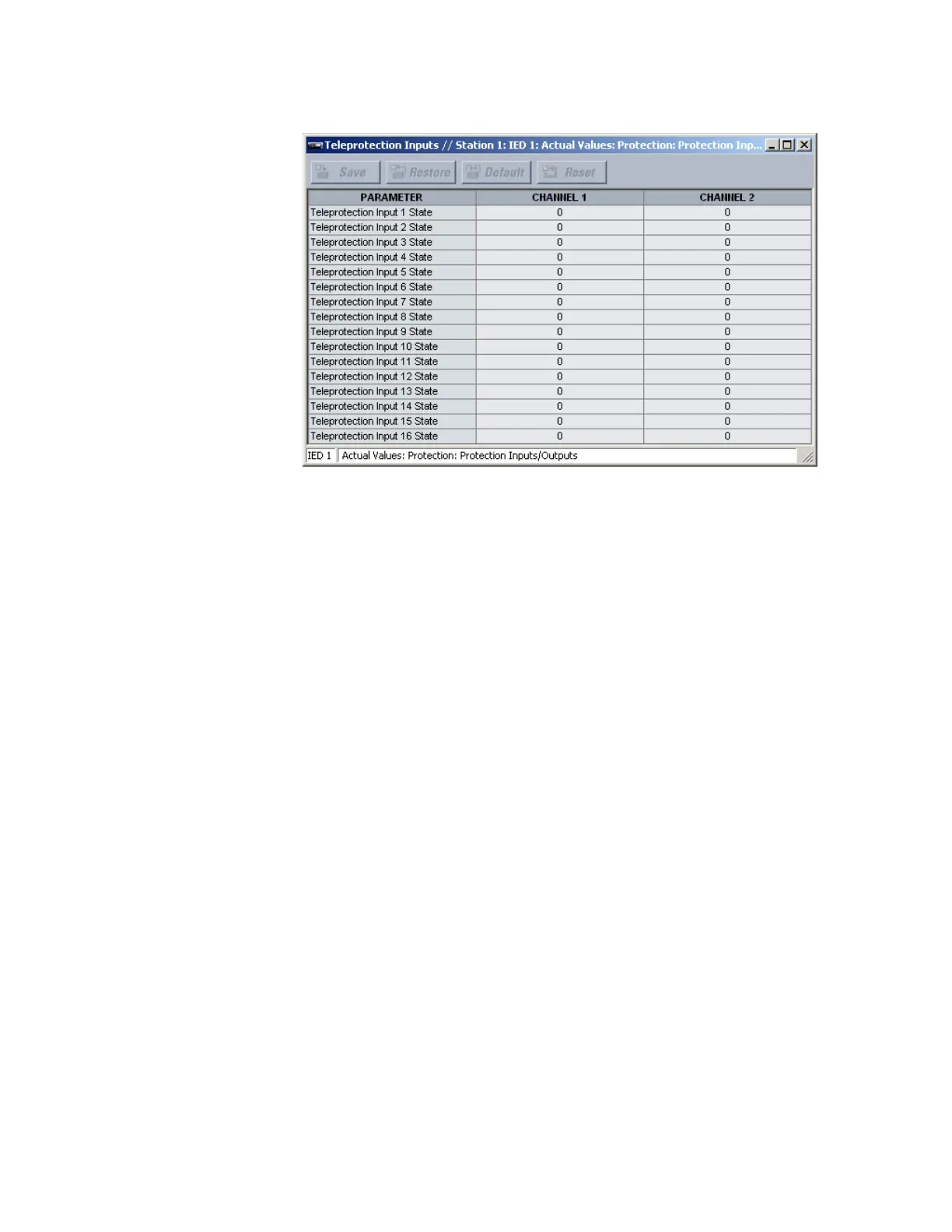
Figure 344: Teleprotection input states
The following actual value is available for all 16 teleprotection inputs on channels 1 and 2.
Teleprotection Input 1 State
Range: Off, On, Latest/On, Latest/Off
This actual value displays the state of the teleprotection input on channels 1 and 2.
The “Latest/On” and “Latest/Off” values freeze the input in case of lost communication. If
the latest state is not known, such as after relay power-up but before the first
communication exchange, then the input defaults to logic 1 for “Latest/On” and logic 0
for “Latest/Off.”
Using shared operands in protection
The EnerVista UR
Plus
Setup software groups the D90
Plus
system into the following eight
primary functions. Each function has its own settings and each generates its own outputs
in the form of operands.
• Communications
•Protection
•Automation
• Digital fault recorder (DFR)
• Metering
• Equipment manager
•Self-tests
• Front panel interface (HMI)
It is often desirable for an output from an element within one function to be available to an
element within another function. For example, it can be useful for the digital fault recorder
to record the output operands of any protection element. Consequently a fixed,
predetermined set of operands is available to each function, as shown.