594 D90
PLUS
LINE DISTANCE PROTECTION SYSTEM – INSTRUCTION MANUAL
MIMIC DIAGRAM EDITOR CHAPTER 12: LOCAL INTERFACE
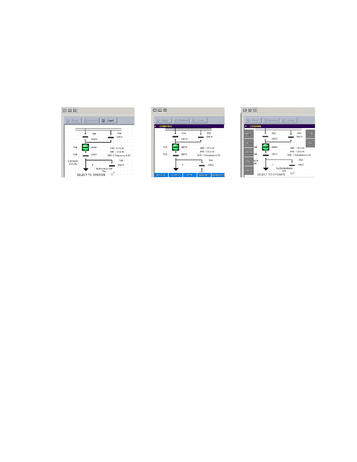
• Overview mode — Provides a preview of how the mimic diagram appears on the
overview screen of the front panel interface
• Control mode — Provides a preview of how the mimic diagram appears on the control
screen of the front panel interface
These modes allow the user to ensure that the mimic diagram displays appropriately in all
display screens. The following figure illustrates the viewing modes.
Figure 523: Mimic diagram view modes
Pre-configured mimic diagrams
The EnerVista UR
Plus
Setup software contains a library of 12 pre-configured mimic
diagrams that can be loaded into the mimic diagram editor. Click the Load button to load a
pre-configured mimic diagram from the library. User-created mimic diagrams can also be
saved into this library. The following pre-configured diagrams are available:
• Breaker-and-a-half scheme
• Breaker-and-a-half scheme with breaker disconnects
• Breaker-and-a-half scheme with breaker and line disconnects
• Breaker-and-a-half scheme with breaker, line, and ground disconnects
• Breaker-and-a-half scheme with line disconnect
• Breaker-and-a-half scheme with line and ground disconnects
• Double-bus bypass scheme 1
• Double-bus bypass scheme 2
• Double-bus bypass scheme with line and ground disconnects
• Single-bus scheme
• Single-bus scheme with line disconnect
• Single-bus scheme with line and ground disconnects
Breakers and disconnect switches are pre-assigned to 12 diagrams shown in the following
figures. If a breaker or disconnect switch has not been enabled, then the device displays as
a solid block.
(GLWPRGH 2YHUYLHZPRGH &RQWUROPRGH