CHAPTER 7: PROTECTION CONTROL ELEMENTS
D90
PLUS
LINE DISTANCE PROTECTION SYSTEM – INSTRUCTION MANUAL 365
Figure 306: Overfrequency logic
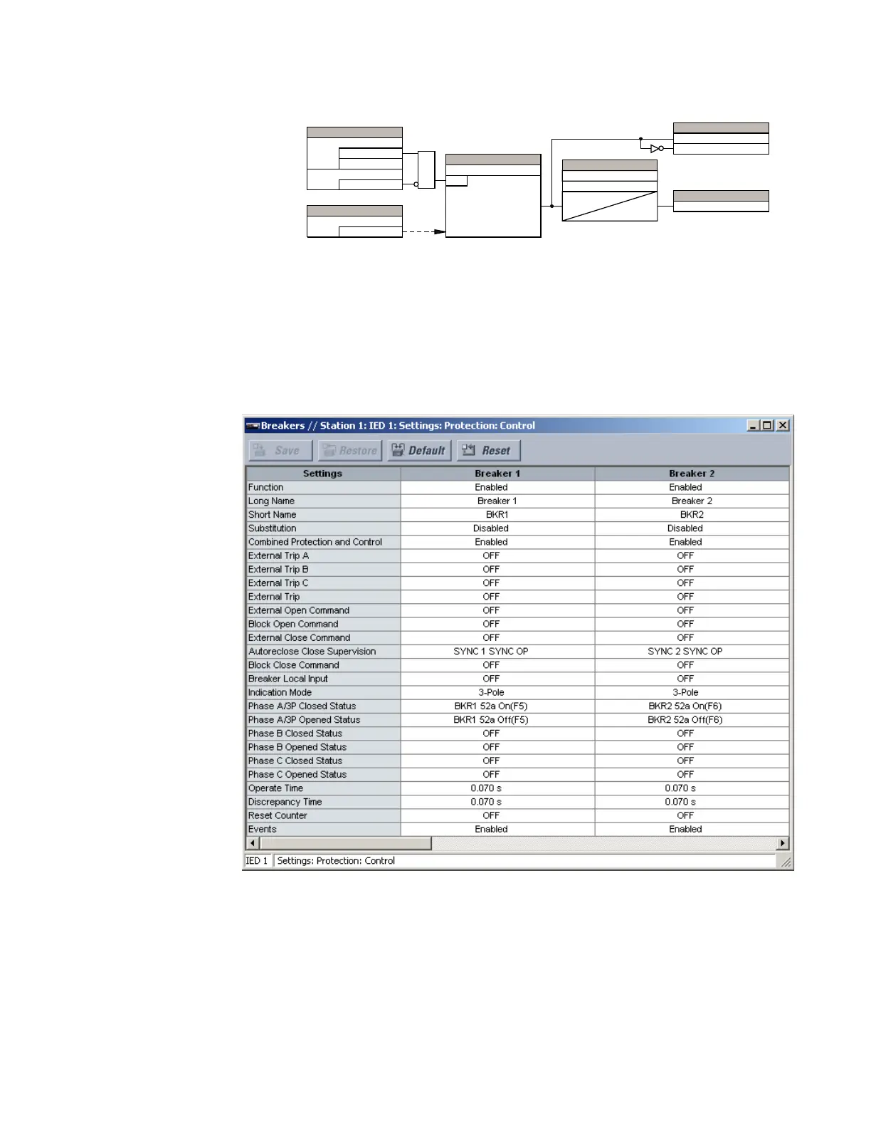
Breaker configuration
The breaker configuration element contains the auxiliary logic for status and serves as the
interface for opening and closing of the breaker from protection and automation
functions. The logic also permits a manual substitution of the position indication.
Select the Settings > Protection > Control > Breakers menu to open the breaker control
configuration window.
Figure 307: Breaker configuration settings
The following settings are available to each of the breakers. The default values outlined
apply to breaker 1.
Function
Range: Enabled, Disabled
Default: Enabled
This setting enables the breaker position indications and control logic. If disabled, all
outputs and front panel indications are switched off.
$&'5
6(77,1*
)UHTXHQF\
6RXUFH
6(77,1*6
(QDEOHG
'LVDEOHG
)XQFWLRQ
2II
%ORFN
$1'
6(77,1*
3LFNXS
581
I 3LFNXS
6(77,1*6
3LFNXS'HOD\
7
SLFNXS
7
UHVHW
5HVHW'HOD\
)/(;/2*,&23(5$1'6
29(5)5(43.3
29(5)5(4'32
29(5)5(423
)/(;/2*,&23(5$1'