CHAPTER 3: INSTALLATION WIRING
D90
PLUS
LINE DISTANCE PROTECTION SYSTEM – INSTRUCTION MANUAL 49
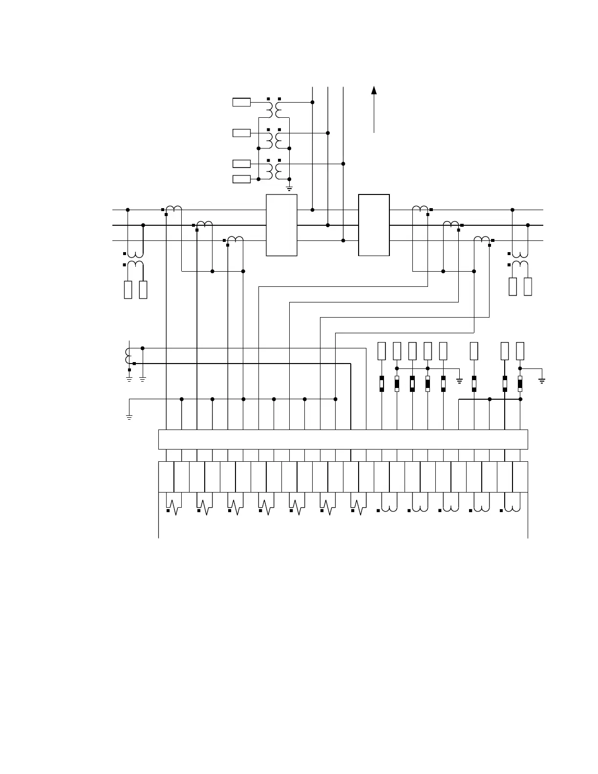
Figure 24: Typical AC module wiring
Contact input and output modules
Each contact input/output module has 24 terminal connections. They are arranged in two
terminals per row, with twelve rows in total. A given row of two terminals can be used for
the outputs of one relay. There are options of using current or voltage detection for feature
supervision, depending on the module ordered.
All inputs and outputs are isolated from one another with each input and output having
two dedicated terminals. Since an entire module row is used for a single contact input or
output, the name is assigned using the module slot position and row number.
-D
$
$
$/
%/
&/
1/
&XUUHQW
SRODUL]DWLRQ
VRXUFH
%
'LUHFWLRQRI
WULSSLQJ
%
$
%
$/
%/
&/
1/
-E
-D
-E
-D
-E
-D
-E
-D
-E
-D
-E
-D
-E
-D
-E
-D
-E
-D
-E
-D
-E
-D
-E
$
%
$&'5
,VRODWLRQDQGWHVWVZLWFKZLWK&7VKRUWLQJ