500 D90
PLUS
LINE DISTANCE PROTECTION SYSTEM – INSTRUCTION MANUAL
USING SHARED OPERANDS IN EQUIPMENT MANAGER CHAPTER 9: EQUIPMENT MANAGER
Events
Range: Enabled, Disabled
Default: Enabled
This setting enables and disables the logging of battery monitoring events in the
sequence of events recorder.
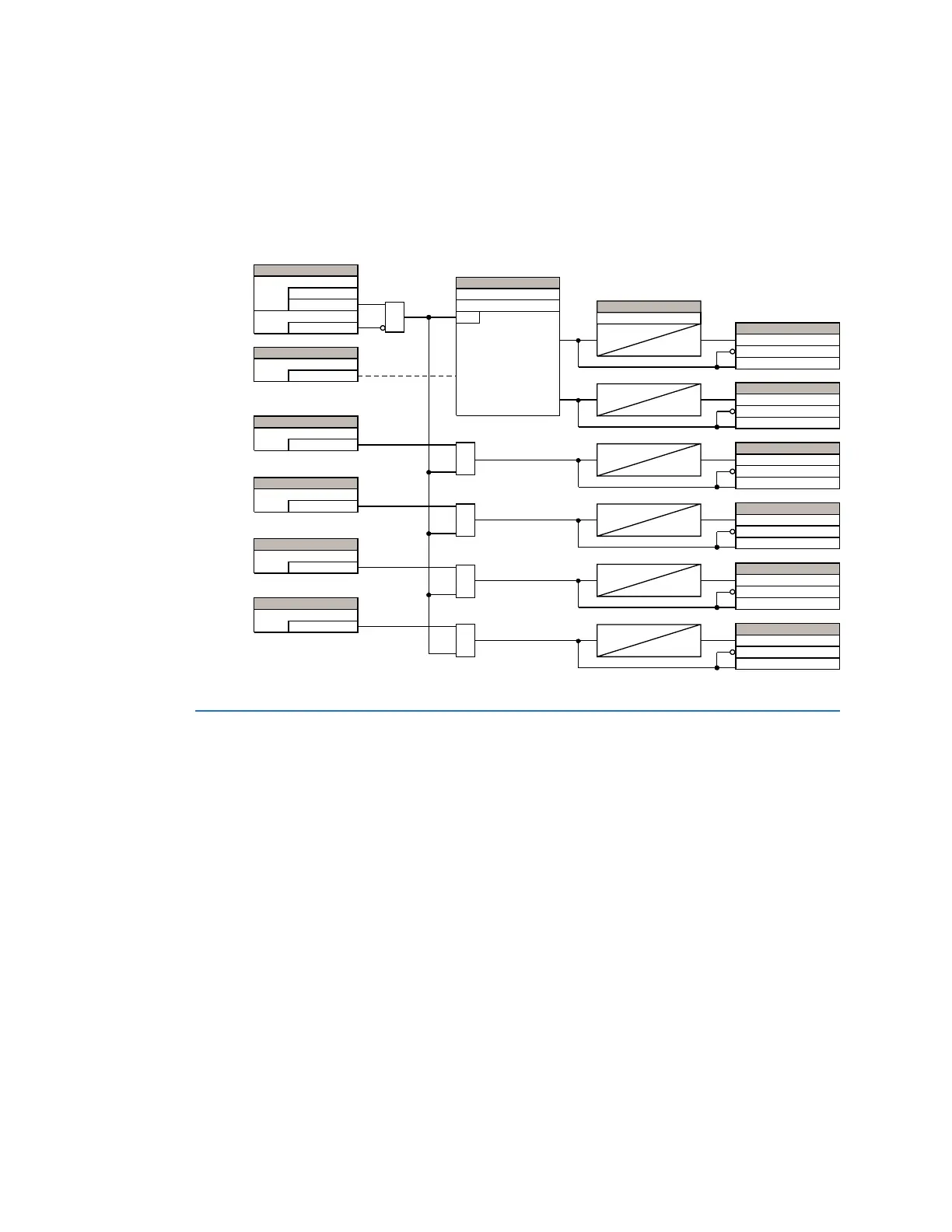
The figure shows the battery monitoring logic diagram.
Figure 434: Battery monitor logic
Using shared operands in equipment manager
The EnerVista UR
Plus
Setup software groups the D90
Plus
system into the following eight
primary functions. Each function has its own settings and each generates its own outputs
in the form of operands.
• Communications
•Protection
•Automation
• Digital fault recorder (DFR)
• Metering
• Equipment manager
•Self-tests
• Front panel interface (HMI)
It is often desirable for an output from an element within one function to be available to an
element within another function. For example, it can be useful for the digital fault recorder
to record the output operands of any protection element. Consequently a fixed,
predetermined set of operands is available to each function, as shown.
$1'
6(77,1*
'LVDEOHG
(QDEOHG
)XQFWLRQ
2II
%ORFN
6(77,1*
2II
,QSXW
6(77,1*
2II
6XSSO\)DLO
$1'
6(77,1*
2II
&KDUJHU)DLO
$1'
6(77,1*
2II
%UHDNHU7ULS
$1'
6(77,1*
2II
'&*URXQG)DXOW
$1'
6(77,1*6
+LJK'&9ROWV
581
9'&!9'&PD[LPXP
/RZ'&9ROWV
9'&!9'&PLQLPXP
6(77,1*
$ODUP'HOD\
7
)/(;/2*,&23(5$1'6
+,*+'&92/7$*(23
+,*+'&92/7$*('32
+,*+'&92/7$*(3.3
7
)/(;/2*,&23(5$1'6
/2:'&92/7$*(23
/2:'&92/7$*('32
/2:'&92/7$*(3.3
7
)/(;/2*,&23(5$1'6
$&6833/<)$,/23
$&6833/<)$,/'32
$&6833/<)$,/3.3
7
)/(;/2*,&23(5$1'6
&+$5*(5)$,/23
&+$5*(5)$,/'32
&+$5*(5)$,/3.3
7
)/(;/2*,&23(5$1'6
'&%.575,323
'&%.575,3'32
'&%.575,33.3
7
)/(;/2*,&23(5$1'6
'&*1')/723
'&*1')/7'32
'&*1')/73.3
$&'5