CHAPTER 7: PROTECTION POWER SYSTEM
D90
PLUS
LINE DISTANCE PROTECTION SYSTEM – INSTRUCTION MANUAL 179
Power system frequency
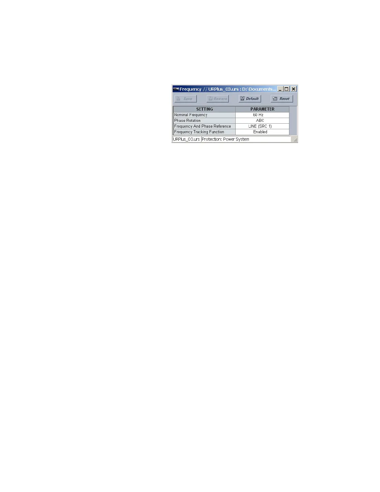
Select the Settings > Protection > Power System > Frequency menu to open the power
system frequency configuration window.
Figure 158: System frequency configuration settings
The following settings are available.
Nominal Frequency
Range: 50 Hz, 60 Hz
Default: 60 Hz
This value is used as a default to set the digital sampling rate if the system frequency
cannot be measured from available signals. This can happen if the signals are not
present or are heavily distorted. Before reverting to the nominal frequency, the
frequency tracking algorithm holds the last valid frequency measurement for a safe
period of time while waiting for the signals to reappear or for the distortions to decay.
Phase Rotation
Range: ABC, ACB
Default: ABC
The phase sequence of the power system is required to properly calculate sequence
components and power parameters. This setting matches the power system phase
sequence and informs the relay of the actual system phase sequence, either ABC or ACB.
The D90
Plus
AC inputs (labeled as A, B, and C) must be connected to system phases A, B,
and C for correct operation.
Frequency and Phase Reference
Range: LINE (SRC 1), BKR 1 (SRC 2), BKR 2 (SRC 3)
Default: LINE (SRC 1)
This setting determines which signal source is used (and hence which AC signal) for
phase angle reference. The AC signal used is prioritized based on the AC inputs
configured for the signal source. Phase voltages takes precedence, followed by auxiliary
voltage, then phase currents, and finally ground current. For three-phase selection,
phase A is used for angle referencing (V
ANGLE_REF
=V
A
), while the Clarke transformation
of the phase signals is used for frequency metering and tracking (V
FREQ
=(2V
A
–V
B
–V
C
)/
3) for better performance during fault, open pole, and VT and CT fail conditions.
The phase reference and frequency tracking AC signals are selected based upon the
source configuration, regardless of whether or not a particular signal is actually applied
to the relay.
The reference signal phase angle always displays zero degrees and all other phase
angles are relative to this signal. If the pre-selected reference signal is not measurable at
a given time, the phase angles are not referenced.
The phase angle referencing is done via a phase locked loop, which can synchronize
independent UR
Plus
-series devices if they have the same AC signal reference. This results
in very precise correlation of time tagging in the event recorder between different
UR
Plus
-series devices provided the relays have an IRIG-B connection.