178 D90
PLUS
LINE DISTANCE PROTECTION SYSTEM – INSTRUCTION MANUAL
POWER SYSTEM CHAPTER 7: PROTECTION
Calculating the power cut-off level
The Current Cutoff Level and the Voltage Cutoff Level settings are used to determine the
metered power cut-off levels. The power cut-off level is calculated as shown here. For delta
connections, the power cut-off is calculated as follows:
Eq. 4
where VT primary = VT secondary × VT ratio and CT primary = CT secondary × CT ratio.
For wye connections, the three-phase and per-phase power cut-off values are calculated
as follows:
Eq. 5
Eq. 6
where VT primary = VT secondary × VT ratio and CT primary = CT secondary × CT ratio.
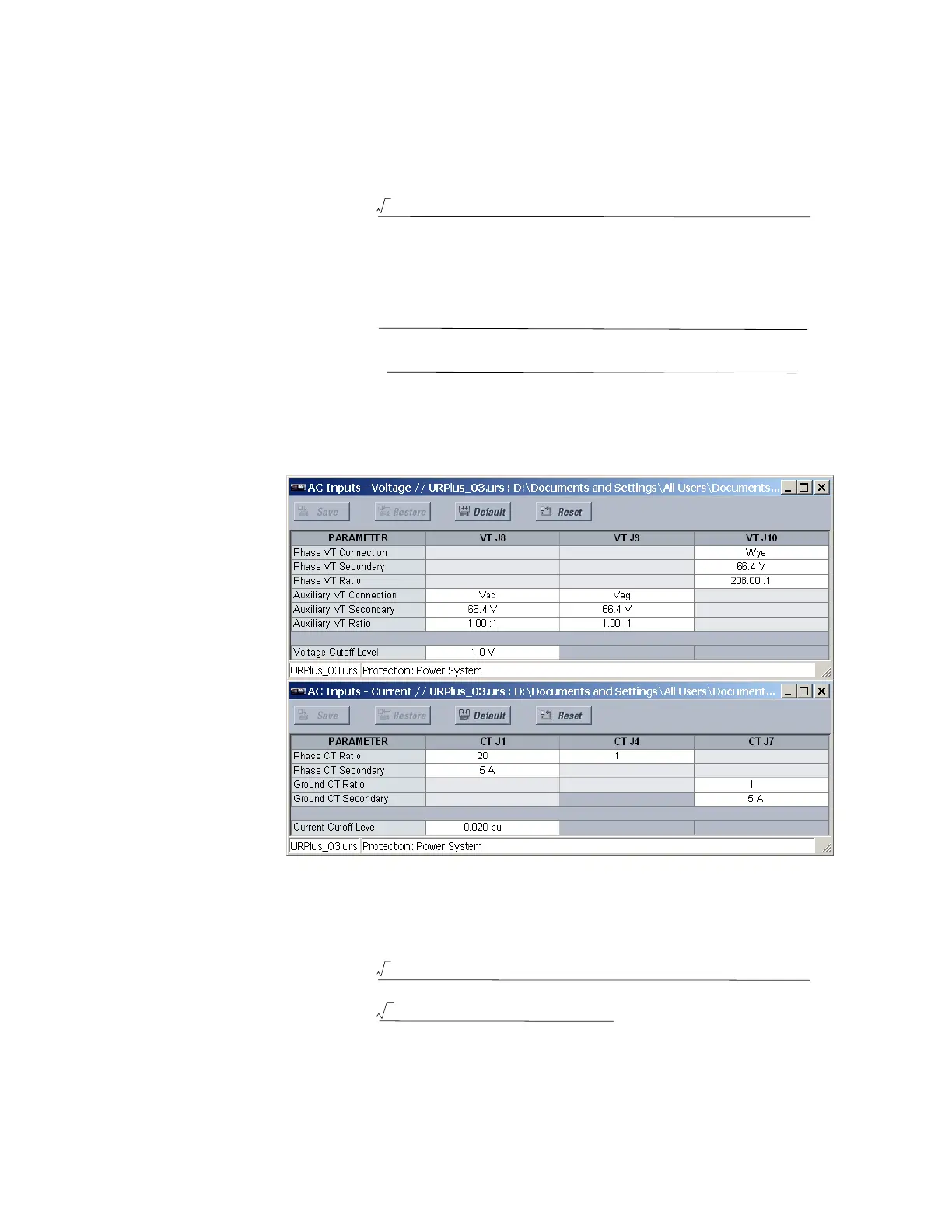
For example, given the following settings:
Figure 157: Typical power system settings
we have:
• CT primary =
Phase CT Ratio × Phase CT Secondary = 20 × 5 A = 100 A.
• VT primary =
Phase VT Ratio × Phase VT Secondary = 208 × 66.4 V = 13811.2 V.
The power cut-off is therefore:
Eq. 7
Any calculated power value below this cut-off does not display. As well, the three-phase
energy data does not accumulate if the total power from all three phases does not exceed
the power cut-off.
7KUHHSKDVH
SRZHUFXWRII
î î î97SULPDU\î&7SULPDU\&XUUHQW&XWRII/HYHO 9ROWDJH&XWRII/HYHO
97VHFRQGDU\
7KUHHSKDVH
SRZHUFXWRII
97VHFRQGDU\
î î î97SULPDU\î&7SULPDU\&XUUHQW&XWRII/HYHO 9ROWDJH&XWRII/HYHO
3HUSKDVH
SRZHUFXWRII
97VHFRQGDU\
&XUUHQW&XWRII/HYHO 9ROWDJH&XWRII/HYHOî î97SULPDU\î&7SULPDU\
7KUHHSKDVH
SRZHUFXWRII
îSXî9î$î9
9
:
î î î97SULPDU\î&7SULPDU\&XUUHQW&XWRII/HYHO 9ROWDJH&XWRII/HYHO
97VHFRQGDU\