106 D90
PLUS
LINE DISTANCE PROTECTION SYSTEM – INSTRUCTION MANUAL
MODBUS COMMUNICATIONS CHAPTER 6: COMMUNICATIONS
See the D90
Plus
Communications Guide for information on developing communication
drivers and for the Modbus memory map. The map is also viewable in a web browser;
enter the IP address of the D90
Plus
in a web browser and click the option. The rest of this
section outlines Modbus configuration settings.
Modbus protocol
The Modbus server can simultaneously support one client over serial RS485 and four
clients over Ethernet. The server is capable of reporting any indication or measurement
and operating any output present in the device. A user-configurable input and output map
is also implemented.
The D90
Plus
operates as a Modbus slave device only.
Select the Settings > Communications > Modbus > Protocol menu to open the Modbus
protocol configuration window.
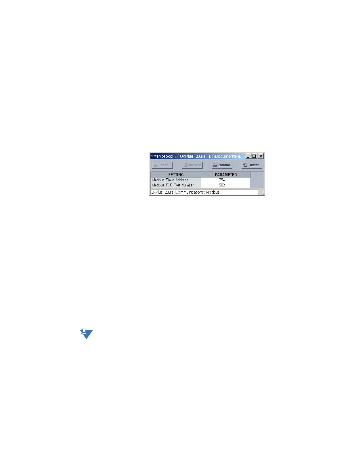
Figure 86: Modbus protocol configuration settings
The following settings are available.
Modbus Slave Address
Range: 1 to 254 in steps of 1
Default: 254
This setting specifies the Modbus slave address for the D90
Plus
. Each device must have a
unique slave address from 1 to 254. Address 0 and addresses from 248 and up are
reserved by the Modbus protocol specification, and so their use here is not
recommended. Address 0 is the broadcast address to which all Modbus slave devices
listen. Addresses do not have to be sequential, but no two devices can have the same
address or conflicts resulting in errors occur. Generally, starting at 1, set each device
added to the link to use the next higher address.
Modbus TCP Port Number
Range: 1 to 65535 in steps of 1
Default: 502
Modbus over TCP/IP can also be used on any of the Ethernet ports. This setting specifies
the Modbus TCP port number for Ethernet communications. Power to the D90
Plus
must
be cycled for changes to this setting to take effect.
NOTE:
Do not set more than one protocol to the same TCP/UDP port number, as this results in
unreliable operation of those protocols.
Modbus user map
The Modbus user map provides read-only access for up to 256 registers. To obtain a
memory map value, enter the address in the
Parameter field (converted from hexadecimal
to decimal format). The corresponding value (if programmed) displays in the
Value field. A
value of “0” in subsequent register
Address lines automatically returns values for the
previous Address lines incremented by 1. An address value of “0” in the initial register
means “none” and values of “0” displays for all registers. Different Address values can be
entered as required in any of the register positions.