40 D90
PLUS
LINE DISTANCE PROTECTION SYSTEM – INSTRUCTION MANUAL
PANEL CUTOUTS CHAPTER 3: INSTALLATION
Panel cutouts
The D90
Plus
is available as a 19-inch rack horizontal mount unit. The modular design allows
the relay to be easily upgraded and repaired by qualified service personnel. The faceplate
is hinged to allow access to the removable modules.
IMPORTANT:
To minimize risk of electrical shock from contact with the power terminals, install the
unit in an electrical closet/enclosure whereby the terminal connections are not readily
accessible.
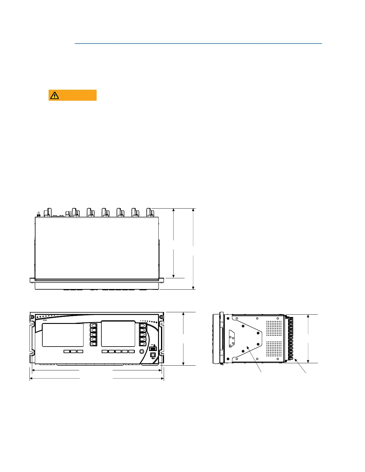
Dimensions
The case dimensions are shown here, along with panel cutout details for panel mounting.
When planning the location of your panel cutout, ensure that provision is made for the
faceplate to swing open without interference to or from adjacent equipment.
Mount the D90
Plus
such that the faceplate sits semi-flush with the panel or switchgear
door, allowing the operator access to the front panel keys and USB communications port.
Secure the D90
Plus
to the panel with the use of four screws supplied with the relay.
Leave a1U (1 rack-unit) space below the chassis when mounting for ventilation and to
allow the front panel to swing open without obstruction.
Figure 16: D90
Plus
dimensions
9.80” [249 mm]
11.43” [290 mm]
7.50” [190 mm]
18.31” [465 mm]
18.86” [479 mm]
870706A2.CDR
7.00” [178 mm]
Mounting bracket
Terminal blocks