588 D90
PLUS
LINE DISTANCE PROTECTION SYSTEM – INSTRUCTION MANUAL
MIMIC DIAGRAM EDITOR CHAPTER 12: LOCAL INTERFACE
Display in Line
Range: 1, 2, 3
Default: 1
This setting specifies the line in the annunciator alarm to display the metered value. It
can be displayed in lines 1, 2, or 3 if the page layout is 3 × 4 or 4 × 6. For 6 × 8 layouts, it
can be displayed in lines 1 or 2.
Mimic diagram editor
The mimic diagram editor allows users to create customized single line diagrams (mimic
diagrams) for the front panel display. Select the Settings > Local HMI > Mimic Diagram
Editor menu to open the editor.
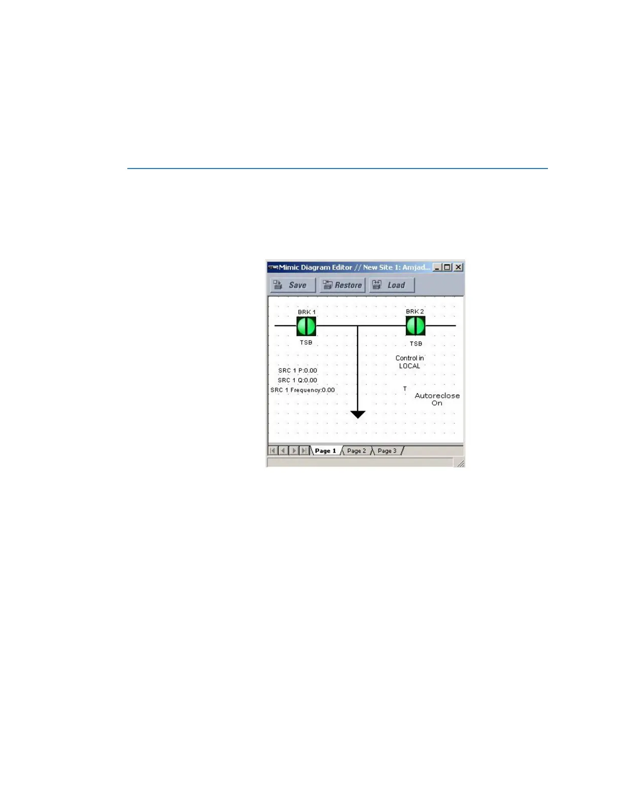
Figure 514: Mimic diagram editor with example of diagram
There is one top level page in the mimic diagram editor.
Each top level diagram has up to 10 sub-level diagrams corresponding to each of the
active components. The sub-level diagram is rendered when the corresponding active
component is selected for operation. To create a sub-level diagram, right-click the breaker
or switch instance in the diagram editor and select the GoTo SLD item. A new diagram is
created and populated with the selected active component and a new tab is added to the
diagram editor.
A components library is included on the upper-right side of the EnerVista software. Options
include dynamic power components, static power components, and text blocks. To create
the single line diagram, select a component, then click the drawing pane to place the
component. Once on the drawing plane, the component can be positioned accordingly.