666 D90
PLUS
LINE DISTANCE PROTECTION SYSTEM – INSTRUCTION MANUAL
SINGLE-POLE TRIPPING CHAPTER 15: THEORY OF OPERATION
This enhanced operation of the pilot-aided schemes is the reason to use a short pilot
scheme priority time when setting the trip output logic. The timer forces the scheme to
wait for a decision from the pilot scheme for a short period of time before accepting any
local trip request. The advantage, however, materializes only if two-bit or four-bit
communications channels are used, and is important only on parallel lines or when the
application requires maximum accuracy of single-pole tripping. In other cases, it is not
recommended to delay the local trip decision.
Cross-country fault example
Assume a single-pole operation application where D90
Plus
IEDs are used to protect a two-
terminal line (terminals T1 and T2) using phase and ground distance zone 1, 2, and 3
elements in a permissive overreaching transfer trip scheme. The performance of the
system with one-bit, two-bit, and four-bit communications channels is outlined for a mid-
line phase A-to-ground fault and a coincident phase B-to-ground fault just behind terminal
T2. Assume also that the reclosers are enabled and reset.
The following protection elements pick up at terminal T1:
• Ground distance zone 1, 2, and 3 for an AG fault
• Ground distance zone 2 and 3 for a BG fault
• Phase distance zone 2 and 3 for an AB fault
The phase selector determines the fault is type ABG at terminal T1. This response is
independent from the distance elements; the phase selector sees two forward faults.
The following protection elements pick up at terminal T2:
• Ground distance zone 1, 2, and 3 for an AG fault
The phase selector determines the fault is type AG at terminal T2. The reverse BG fault is
likely to be ignored.
If a one-bit channel is used, terminal T1 trips three poles but terminal T2 trips phase A only
(see the table), which is undesirable.
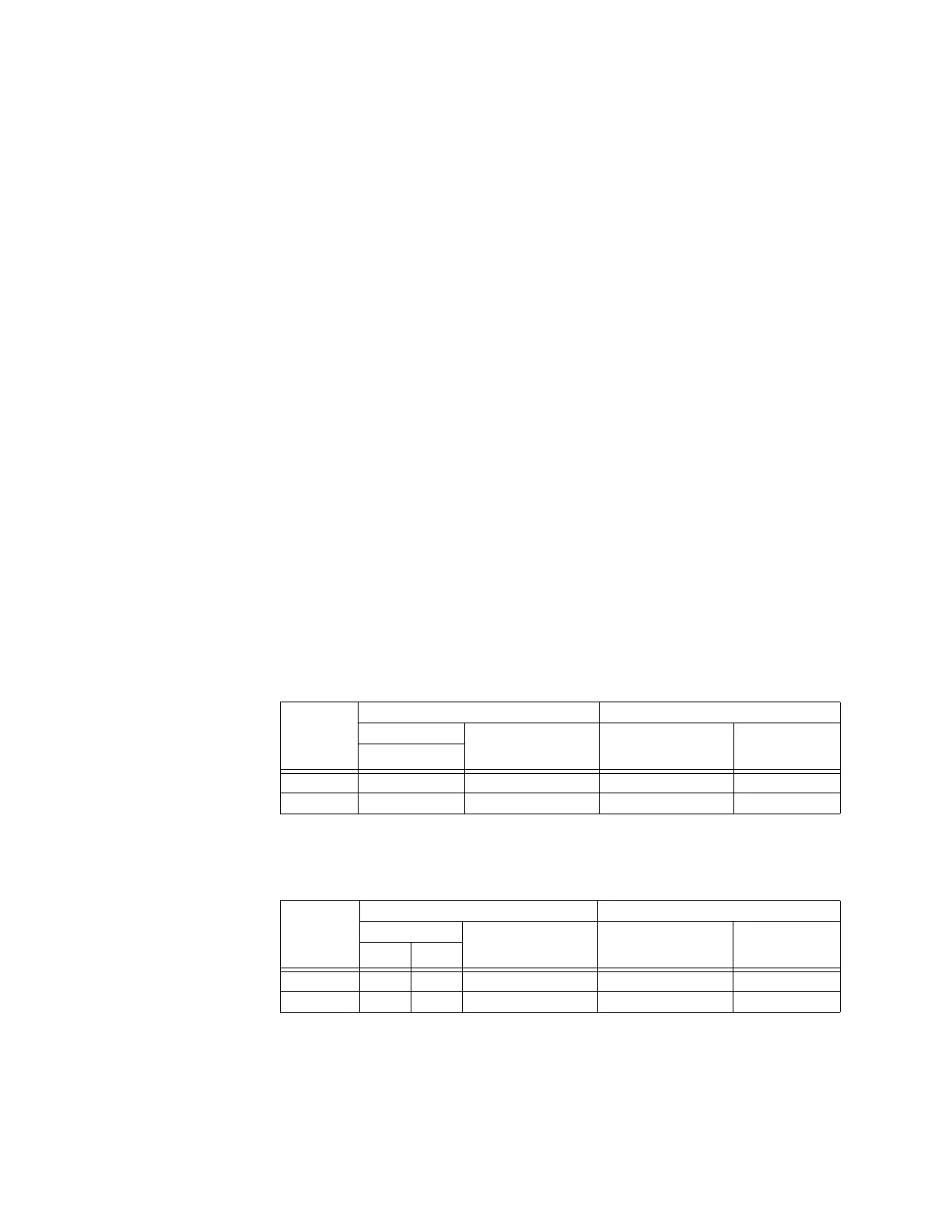
Table 48: Trip table for cross-country fault example, one-bit channel
If a two-bit channel is used, both terminal T1 and T2 trip phase A only (see the following
table), which is the required outcome.
Table 49: Trip table for cross-country fault example, two-bit channel
If a four-bit channel is used, both terminal T1 and T2 trip phase A only (see the following
table), which is the required outcome.
Terminal Remote data Local data
Bit pattern Remote
determination of fault
type
Local determination
of fault type
Trip output
RX1
T1 1 Any MULTI-P (ABG) TRIP 3-POLE
T2 1 Any AG TRIP PHASE A
Terminal Remote data Local data
Bit pattern Remote
determination of fault
type
Local determination
of fault type
Trip output
RX1 RX2
T1 1 0 AG ABG TRIP PHASE A
T2 1 1 ABG AG TRIP PHASE A