CHAPTER 7: PROTECTION CONTROL ELEMENTS
D90
PLUS
LINE DISTANCE PROTECTION SYSTEM – INSTRUCTION MANUAL 377
Consider the configuration shown.
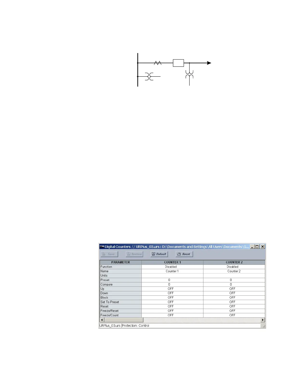
Figure 316: Breaker flashover application example
The source 1 (SRC1) phase currents are CTs and phase voltages are bus VTs. The source 2
(SRC2) phase voltages are line VTs. Contact input 1 is set as the breaker 52a contact
(optional).
The conditions prior to flashover detection are
1. ∆VA is greater than pickup
2. VAg, VBg, or VCg is greater than the pickup setting
3. IA, IB, IC = 0; no current flows through the breaker
4. 52a status = 0 (optional)
The conditions at flashover detection are
1. ∆VA is less than pickup
2. VAg, VBg, or VCg is lower than the pickup setting
3. IA, IB, or IC is greater than the pickup current flowing through the breaker
4. 52a status = 0 (optional)
Digital counters
There are eight identical digital counters in the D90
Plus
. A digital counter counts the
number of state transitions from logic 0 to logic 1. It counts operations, such as element
pickup, changes of state of an external contact (for example, a breaker auxiliary switch), or
pulses from a watt-hour meter.
Select the Settings > Protection > Control > Digital Counters menu to open the digital
counters configuration window.
Figure 317: Digital counters configuration settings
The following settings are available for each digital counter.
$&'5
97V
97V
/LQH)HHGHU
%UHDNHU
&7V
%XV