CHAPTER 7: PROTECTION CONTROL ELEMENTS
D90
PLUS
LINE DISTANCE PROTECTION SYSTEM – INSTRUCTION MANUAL 333
Dropout Delay
Range: 0.000 to 60.000 seconds in steps of 0.001
Default: 0.000 seconds
This setting specifies the delay by which to extend the FlexMatrix dropout.
Latching
Range: Enabled, Disabled
Default: Disabled
When this setting is enabled, the FlexMatrix output is latched until the reset input is
asserted.
Reset
Range: any FlexLogic operand or shared operand
Default: OFF
Assertion of the operand assigned to this setting resets the FlexMatrix output when
latching is enabled.
Events
Range: Enabled, Disabled
Default: Enabled
This setting enables and disables the logging of FlexMatrix events in the sequence of
events recorder.
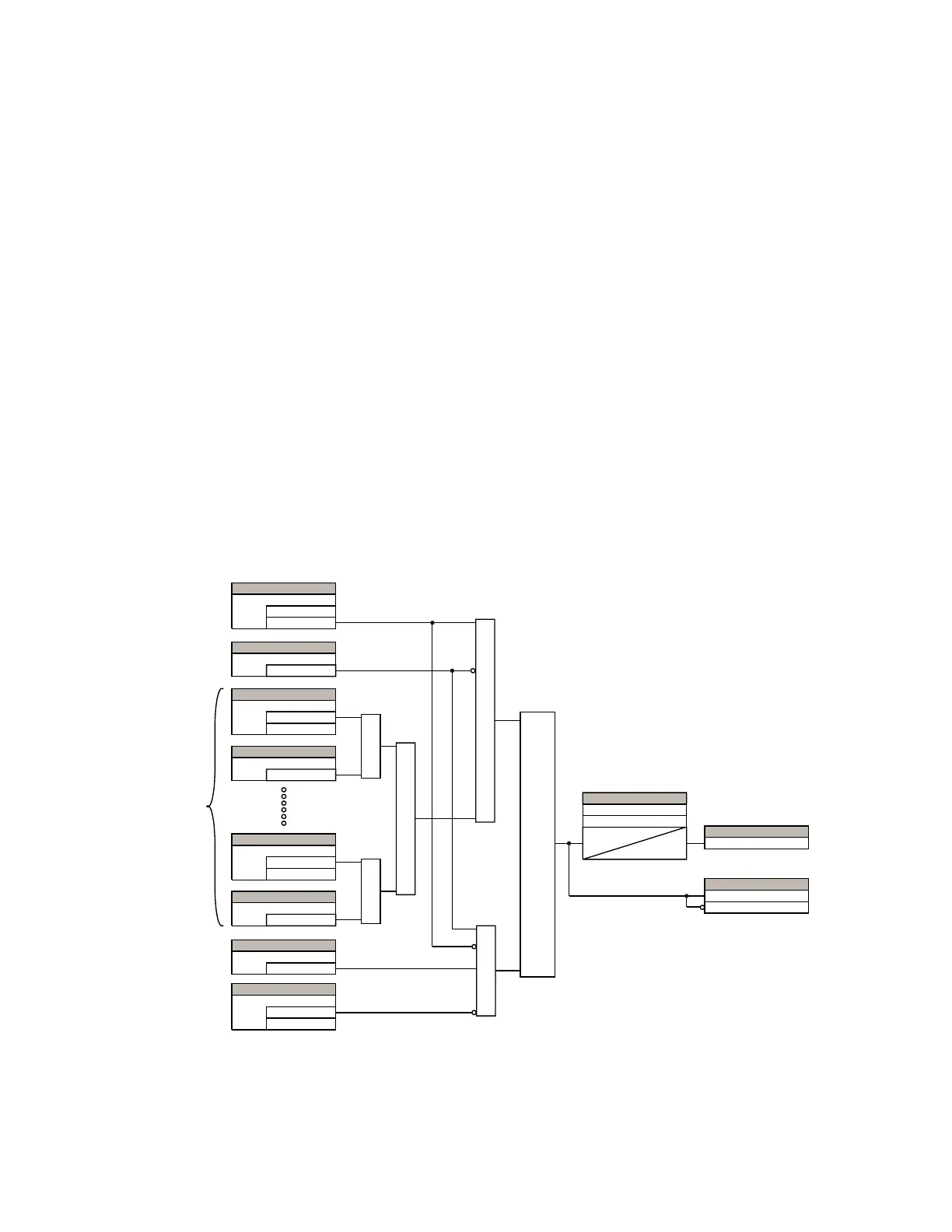
The figure shows the logic for FlexMatrix 1. The logic is identical for all eight FlexMatrix
elements.
Figure 272: FlexMatrix logic
VT fuse failure
Every signal source includes a fuse failure scheme.
$&'5
1RQYRODWLOH
VHWGRPLQDQW
6(77,1*
2))
%ORFN
6(77,1*
(QDEOHG
'LVDEOHG
)XQFWLRQ
6(77,1*
2))
,QSXW
6(77,1*
(QDEOHG
'LVDEOHG
,QSXW(QDEOH
6(77,1*
2))
,QSXW
6(77,1*
(QDEOHG
'LVDEOHG
,QSXW(QDEOH
$1'
$1'
25
5HSHDWHG
IRUDOO
LQSXWV
$1'
6(77,1*
2))
5HVHW
6(77,1*
(QDEOHG
'LVDEOHG
/DWFKLQJ
25
/DWFK
6
5
6(77,1*6
7
3.3
7
'32
)/(;/2*,&23(5$1'6
)/(;0$73.3
)/(;0$7'32
3LFNXS'HOD\
'URSRXW'HOD\
)/(;/2*,&23(5$1'
)/;0$723