656 D90
PLUS
LINE DISTANCE PROTECTION SYSTEM – INSTRUCTION MANUAL
SINGLE-POLE TRIPPING CHAPTER 15: THEORY OF OPERATION
reset. If the zone 1 BG element picks up, or the zone 2 BG element picks up resulting in
operation of the POTT scheme, no trip command is issued until the AR FORCE 3-P TRIP is
asserted. This happens 1.25 cycles after the first trip. If at this time or any time later a
request for trip is placed (due to an evolving fault), a three-pole trip is initiated. The TRIP 1-
POLE operand is de-asserted by the TRIP 3-POLE operand, resetting the open pole detector.
Shortly all three-poles are opened.
When the dead time expires, the recloser signals the breaker control to close the breaker.
At this time, all the protection elements are operational, as the open pole detector is not
blocking any elements. If the line-side VTs are used, the line pickup element is armed as
well. If there is a fault on the line, these elements pick up the fault and issue the next
request for trip. This request results in three-pole trip as the AR FORCE 3-P TRIP is still
asserted.
The response of the system from this point is as described above for the second trip,
except that the recloser goes to lockout upon the next initiation (depending on the number
of shots programmed).
Phase selection
The D90
Plus
uses phase relations between current symmetrical components for phase
selection. First, the algorithm validates if there is enough zero-sequence current, positive-
sequence current, and negative-sequence current for reliable analysis. The comparison is
adaptive; that is, the magnitudes of the three symmetrical components used mutually as
restraints confirm if a given component is large enough to be used for phase selection.
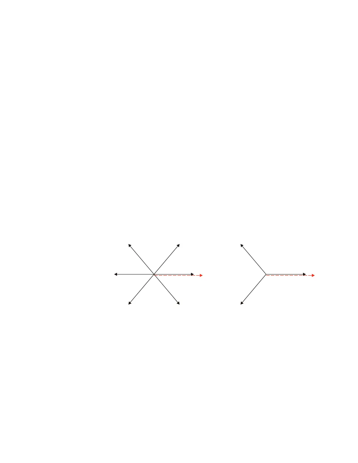
Once the current magnitudes are validated, the algorithm analyzes phase relations
between the negative-sequence and positive-sequence currents and negative-sequence
and zero-sequence currents (when applicable), as illustrated.
Figure 562: Phase selection principle (ABC phase rotation)
Due to dual comparisons, the algorithm is very secure. For increased accuracy and to
facilitate operation in weak systems, the pre-fault components are removed from the
analyzed currents. The algorithm is very fast and ensures proper phase selection before
any of the correctly set protection elements operate.
Under unusual circumstances, such as weak-infeed conditions with the zero-sequence
current dominating during any ground fault, or during cross-country faults, the current-
based phase selector does not always recognize any of the known fault pattern. If this is
the case, voltages are used for phase selection. The voltage algorithm is the same as the
current-based algorithm; for example, phase angles between the zero-sequence,
negative-sequence, and positive-sequence voltages are used. The pre-fault values are
subtracted prior to any calculations.
The pre-fault quantities are captured and the calculations start when the disturbance
detector (ANSI 50DD) operates.
$&'5
$%
$%*
&$
&$*
%&
%&*
$*
$*
%&*
,B
)
,B
)
,B
)
,B
)
%*
&*
$%*
&*
%*
&$*