CHAPTER 8: AUTOMATION AUTOMATION INPUTS AND OUTPUTS
D90
PLUS
LINE DISTANCE PROTECTION SYSTEM – INSTRUCTION MANUAL 463
Figure 391: Automation virtual input logic
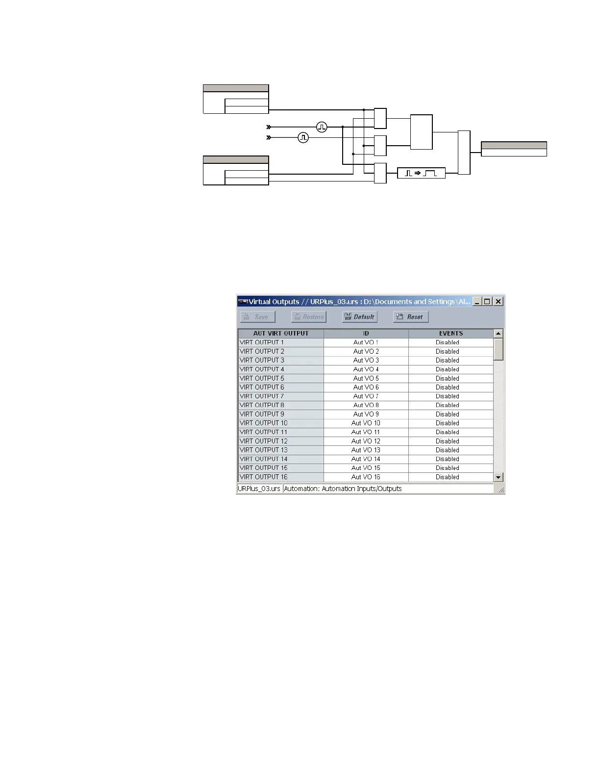
Automation virtual outputs
There are 255 virtual outputs that can be assigned via automation logic. Virtual outputs
are resolved in each pass through the evaluation of the automation logic equations.
Select the Settings > Automation > Automation Inputs/Outputs > Virtual Outputs menu
to access the automation virtual output configuration settings.
Figure 392: Automation virtual output settings
The following settings are available for each automation virtual output. If not assigned, the
virtual output is forced to off (logic 0).
ID
Range: up to 12 alphanumeric characters
Default: Aut VO 1
This setting specifies an identifier that can be assigned to each automation virtual
output.
Events
Range: Enabled, Disabled
Default: Disabled
If this setting is “Enabled,” every change in the automation virtual output state triggers
an event in the sequence of events recorder.
As an example, if automation virtual output 1 is the trip signal from automation logic and
the trip relay is used to signal events, the settings are programmed as follows.
9LUWXDOLQSXWWR2))
9LUWXDO WR21 LQSXW
$1'
$&'5
6(77,1*
'LVDEOHG
(QDEOHG
)XQFWLRQ
6(77,1*
/DWFKHG
6HOI5HVHW
7\SH
$1'
$1'
/DWFK
6
5
25
)/(;/2*,&23(5$1'
9LUW,S