CHAPTER 10: DIGITAL FAULT RECORDER DISTURBANCE RECORDER
D90
PLUS
LINE DISTANCE PROTECTION SYSTEM – INSTRUCTION MANUAL 521
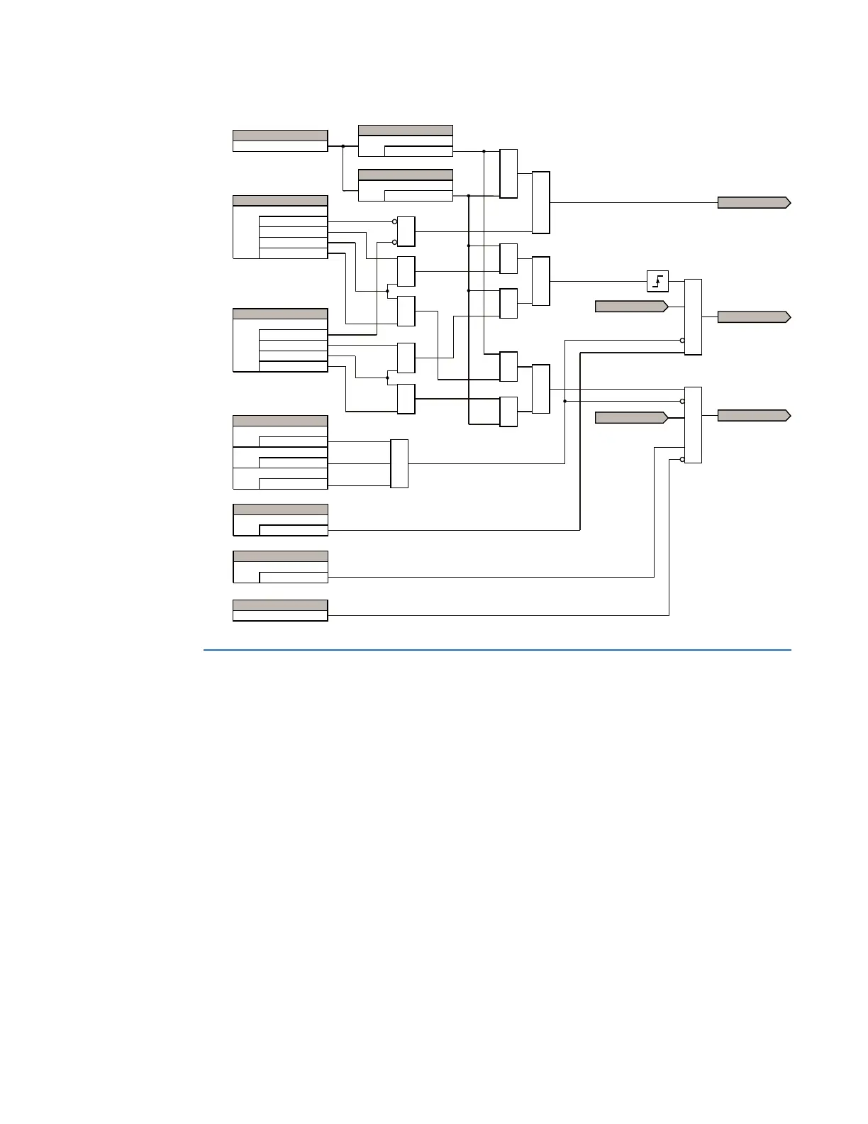
Figure 452: Analog channel trigger logic
Disturbance recorder
The disturbance recorder is designed to capture long duration events, such as power
swings, at a resolution of one sample per cycle. Under normal operation, the disturbance
recorder is capturing continuously the pre-event data and storing this data in memory.
When a trigger is received, the disturbance recorder captures the data during the post-
event period. Both the pre-event and post-event data are stored as a record in non-volatile
memory within the D90
Plus
.
The disturbance recorder captures the user-configured digital and analog channels, each
of which can be used to trigger or re-trigger the disturbance recorder. A re-trigger captures
an additional record but with no pre-event data. Triggered and re-triggered records are
merged into a single file, and the maximum number of re-triggers for a particular event is
user-programmable.
25
25
IURPWUDQVLHQWUHFRUGHU
WULJJHUORJLF
$&'5
$1/*&+$&7,9(
6(77,1*
9DOXH!+LJK3LFNXS
+LJK3LFNXS
)/(;/2*,&23(5$1'
5(75,**(56 0$;
6(77,1*
9DOXH/RZ3LFNXS
/RZ3LFNXS
6(77,1*
2II
+LJK7ULJJHULQJ
7ULJJHU2QO\
7ULJJHU5H7ULJJHU
5H7ULJJHU2QO\
25
25
6(77,1*
2II
+LJK7ULJJHULQJ
7ULJJHU2QO\
7ULJJHU5H7ULJJHU
5H7ULJJHU2QO\
25
25
6(77,1*6
'LVDEOHG
)XQFWLRQ
2II
%ORFN7ULJJHU
2II
%ORFN
25
6(77,1*6
(QDEOHG
7ULJJHU
6(77,1*6
(QDEOHG
5H7ULJJHU
$&78$/9$/8(
9DOXH
$1'
$1'
$1'
25
$1'
$1'
25
$1'
$1/*&+5(75,**(5
5(75,**(56839
$1'
75,**(56839
$1/*&+75,**(5
IURPWUDQVLHQWUHFRUGHU
WULJJHUORJLF