636 D90
PLUS
LINE DISTANCE PROTECTION SYSTEM – INSTRUCTION MANUAL
DISTANCE ELEMENTS CHAPTER 15: THEORY OF OPERATION
Table 15-18: Non-directional quadrilateral ground distance functions
Memory polarization
All distance functions use memory polarization. The positive-sequence voltage, either
memorized or actual, is used as a polarizing signal. The memory is established when the
positive-sequence voltage remains above 80% of its nominal value for five power system
cycles. The memory voltage is a two-cycle old voltage.
Once established, the memory is applied for the user-specified time interval. The memory
timer is started when the voltage drops below 80% of nominal or when the user-
programmable condition is asserted to force memory polarization. After the memory
expires, the D90
Plus
checks the magnitude of the actual positive-sequence voltage. If it is
greater than 10% of nominal, the actual voltage is used; if it is less than 10% of nominal,
the memory voltage continues to be used.
A provision is added to force self-polarization from any user-programmable condition.
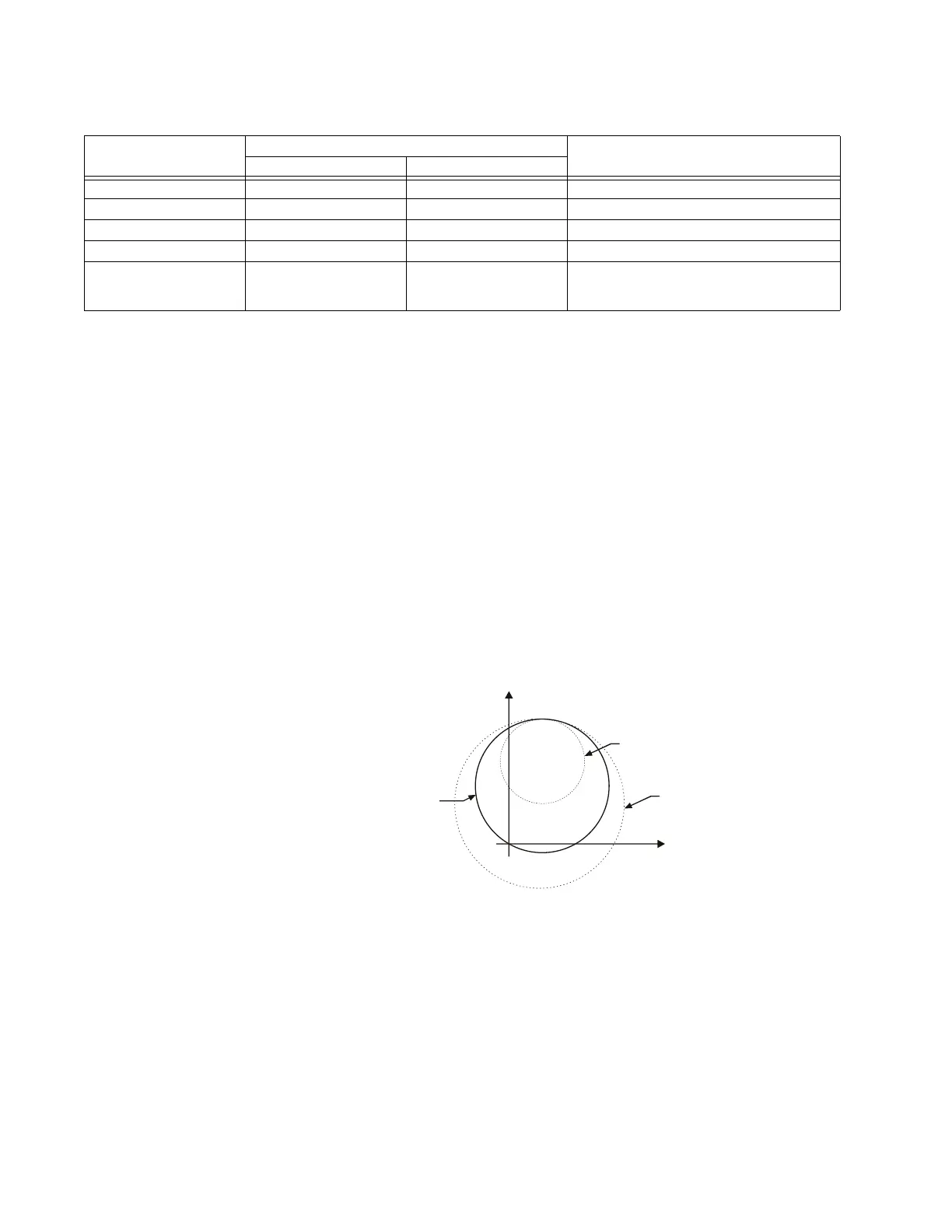
The memory-polarized mho has an extra directional integrity built-in as illustrated in the
following figure. The self-polarized mho characteristic is shifted in the reverse direction for
a forward fault by an amount proportional to the source impedance, and in the forward
direction for a reverse fault.
Figure 551: Dynamic shift of the memory-polarized mho characteristic
The same desirable effect of memory polarization applies to the directional comparator of
the quadrilateral characteristic.
Characteristic Comparator inputs Limit angle
Input 1 Input 2
Forward reactance I × Z – Vj × I_0 × e
jΘ
or j × I_2 × e
jΘ
Comparator limit
Reverse reactance I_0 × Z
D
–j × I_0 × e
jΘ
or –j × I_2 × e
jΘ
Comparator limit
Right blinder I × Z
R
– VI × Z
R
90°
Left blinder I × Z
L
– VI × Z
L
90°
Fault type I_0 I_2 50° (removed during open pole conditions or
when 3I_0 > overcurrent supervision and
I_2<cutoff)
5
0HPRU\SRODUL]HGPKR
UHYHUVHIDXOW
0HPRU\SRODUL]HGPKR
IRUZDUGIDXOW
;
$&'5
6HOISRODUL]HGPKR