CHAPTER 15: THEORY OF OPERATION GROUND DIRECTIONAL OVERCURRENT THEORY
D90
PLUS
LINE DISTANCE PROTECTION SYSTEM – INSTRUCTION MANUAL 647
Consequently, the following signals are applied to the phase AB distance element:
Eq. 77
Eq. 78
This results in the following apparent impedance:
Eq. 79
The apparent impedance calculated in the equation is a correct measure of the distance
from the VT location to the fault. For relay location H, this certainly includes the positive-
sequence impedance of the transformer.
Eq. 80
Therefore, 0.127 Ω ∠90° + 0.05779 Ω ∠85° = 0.1847 Ω ∠88.4° on the primary side or 2.569
Ω ∠88.4° on the secondary side.
This example illustrates how the D90
Plus
maintains correct reach for fault behind power
transformers. When installed at location X, set the D90
Plus
reach to 0.687 Ω ∠85°
secondary to cover the fault shown in the figure. When installed at location H, set the
D90
Plus
reach to 2.569 Ω ∠88.4° to ensure exactly the same coverage.
Ground directional overcurrent theory
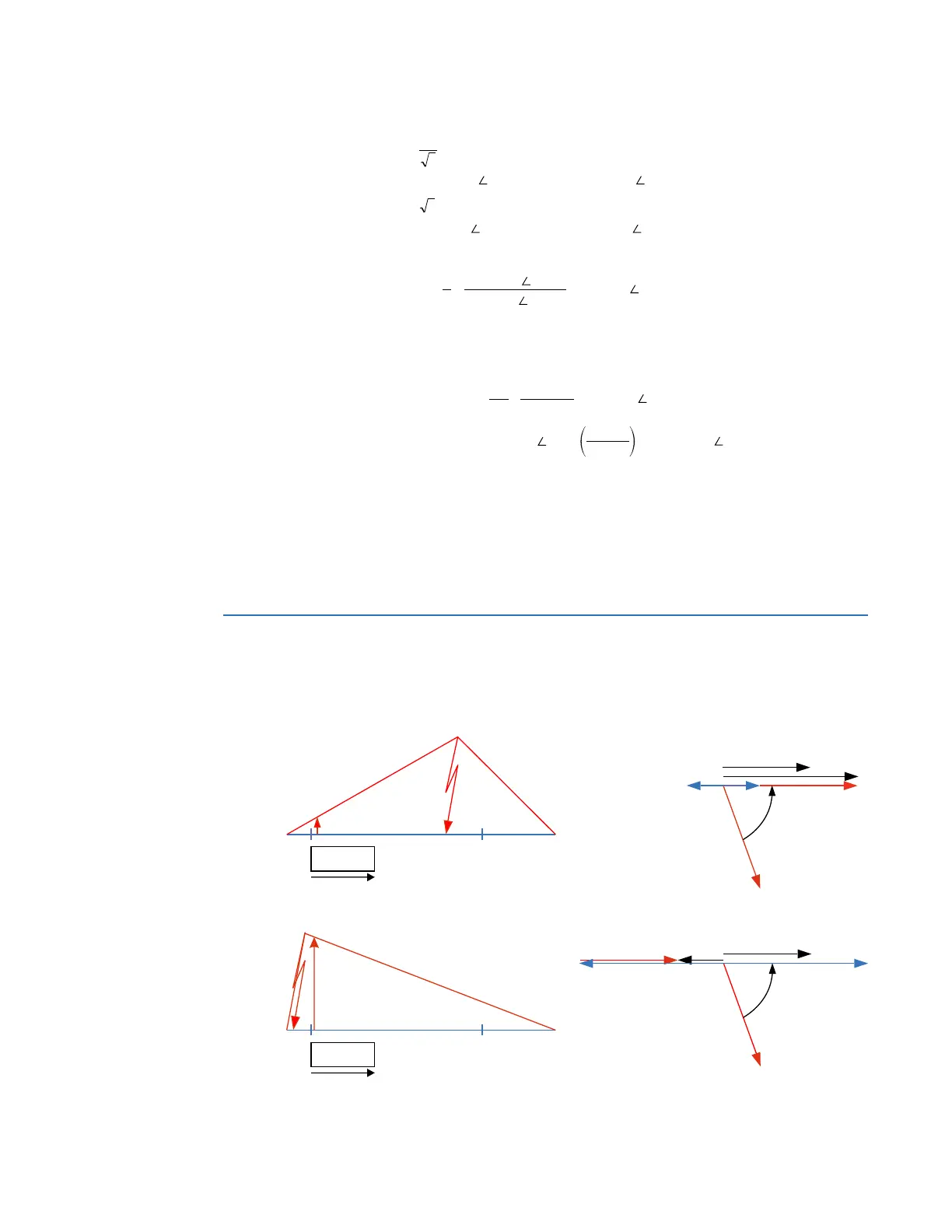
Consider the negative-sequence directional overcurrent element. As illustrated here, the
negative-sequence voltage can be low during internal fault conditions.
Figure 556: Offset impedance augmentation
²
%&$%
999
N9SULPDU\RU9VHFRQGDU\
²
%
,,
N$²SULPDU\RU$²VHFRQGDU\
,
9
=
$33
N9
N$²
űVHFRQGDU\
ű
î
N9
N9
09$
=
7
DWN9
=
/
DWN9 űî
N9
ű
$&'5
85 ,('
3OXV
9B!
,=Bî B
/,1(
,B
(&$
,=Bî
9B²B9
6BSRO
6BRS
,B
(&$
,=Bî
9B
² B9
6BSRO
6BRS
² B9
85 ,('
3OXV