646 D90
PLUS
LINE DISTANCE PROTECTION SYSTEM – INSTRUCTION MANUAL
PHASE DISTANCE APPLIED TO POWER TRANSFORMERS CHAPTER 15: THEORY OF OPERATION
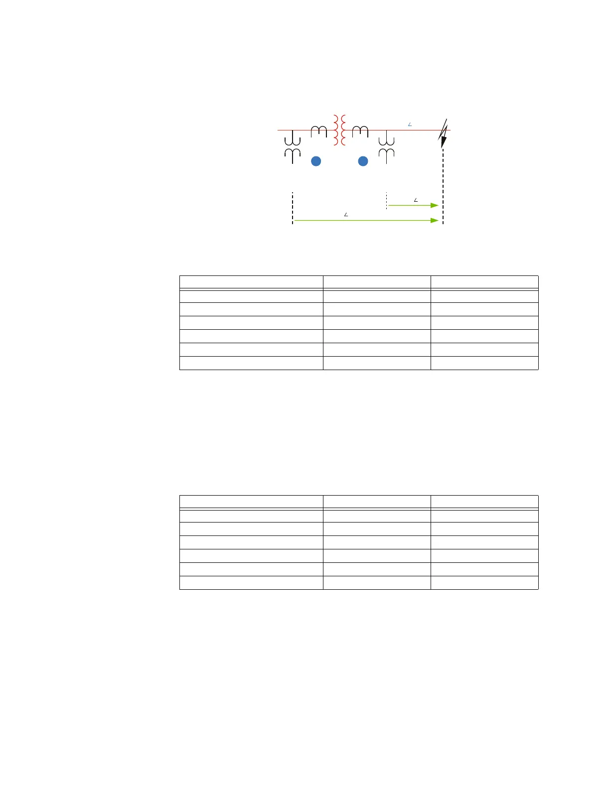
Figure 555: Example system configuration
The D90
Plus
input signals at point X are shown in the following table.
Table 26: Input signals at point X for example system with power transformers
If installed at location X, the D90
Plus
uses the following input signals for its phase AB
distance element.
V = V
AB
= 77.402 kV ∠57.5° primary or 29.49 V ∠57.5° secondary.
I = I
A
– I
B
= 2.576 kA ∠–27.6° primary or 42.93 A ∠–27.6° secondary.
And consequently, the D90
Plus
sees the following apparent impedance:
Z
APP
= V / I = 30.05 Ω ∠85° primary or 0.687 Ω ∠85° secondary
If applied at location H, the D90
Plus
input signals are shown in the following table.
Table 27: Input signals at point H for example system with power transformers
The following settings are applied in the D90
Plus
:
Transformer Voltage Connection: “Dy11”
Transformer Current Connection: “Dy11”
Input Primary Secondary
V
A
100.4 kV ∠–7.32° 38.25 V ∠–7.32°
V
B
97.23 kV ∠–53.4° 37.04 V ∠–53.4°
V
C
181.8 kV ∠–150.0° 69.26 V ∠–150.0°
I
A
1.288 kA ∠–27.6° 21.47 A ∠–27.6°
I
B
1.288 kA ∠152.4° 21.47 A ∠152.4°
I
C
00
Input Primary Secondary
V
A
7.854 kV ∠–5.59° 69.95 V ∠–5.59°
V
B
6.269 kV ∠–120.1° 54.52 V ∠–120.1°
V
C
7.751 kV ∠125.5° 65.84 V ∠125.5°
I
A
16.976 kA ∠–27.6° 10.61 A ∠–27.6°
I
B
33.952 kA ∠152.4° 21.11 A ∠152.4°
I
C
16.976 kA ∠–27.6° 10.61 A ∠–27.6°
$&'5
$%
Z\HODJ
ű
ű
09$
N9N9
=
/
ű
97 N99
&7
97 N99
&7
GHOWD
+;