CHAPTER 7: PROTECTION CONTROL ELEMENTS
D90
PLUS
LINE DISTANCE PROTECTION SYSTEM – INSTRUCTION MANUAL 291
where
m is a multiplier defined by the multiplier setting
S
ref
is the pickup setting
S
op
is the operating power at the time. This timer starts after the definite time timer
expires.
The four FlexCurves allow for custom user-programmable time characteristics. When
working with FlexCurves, the element uses the operate to pickup ratio, and the multiplier
setting is not applied:
Eq. 39
Again, the FlexCurve timer starts after the definite time timer expires.
Multiplier
Range: 0.01 to 2.00 seconds in steps of 0.01
Default: 1.00 seconds
This setting is applicable if the wattmetric
Curve setting is “Inverse” and defines the
multiplier factor for the inverse time delay.
Block
Range: any FlexLogic operand
Default: Off
Assertion of the FlexLogic operand assigned to this setting blocks operation of the
wattmetric zero-sequence directional ground fault element.
Events
Range: Enabled, Disabled
Default: Disabled
This setting enables and disables the logging of wattmetric zero-sequence directional
ground fault events in the sequence of events recorder.
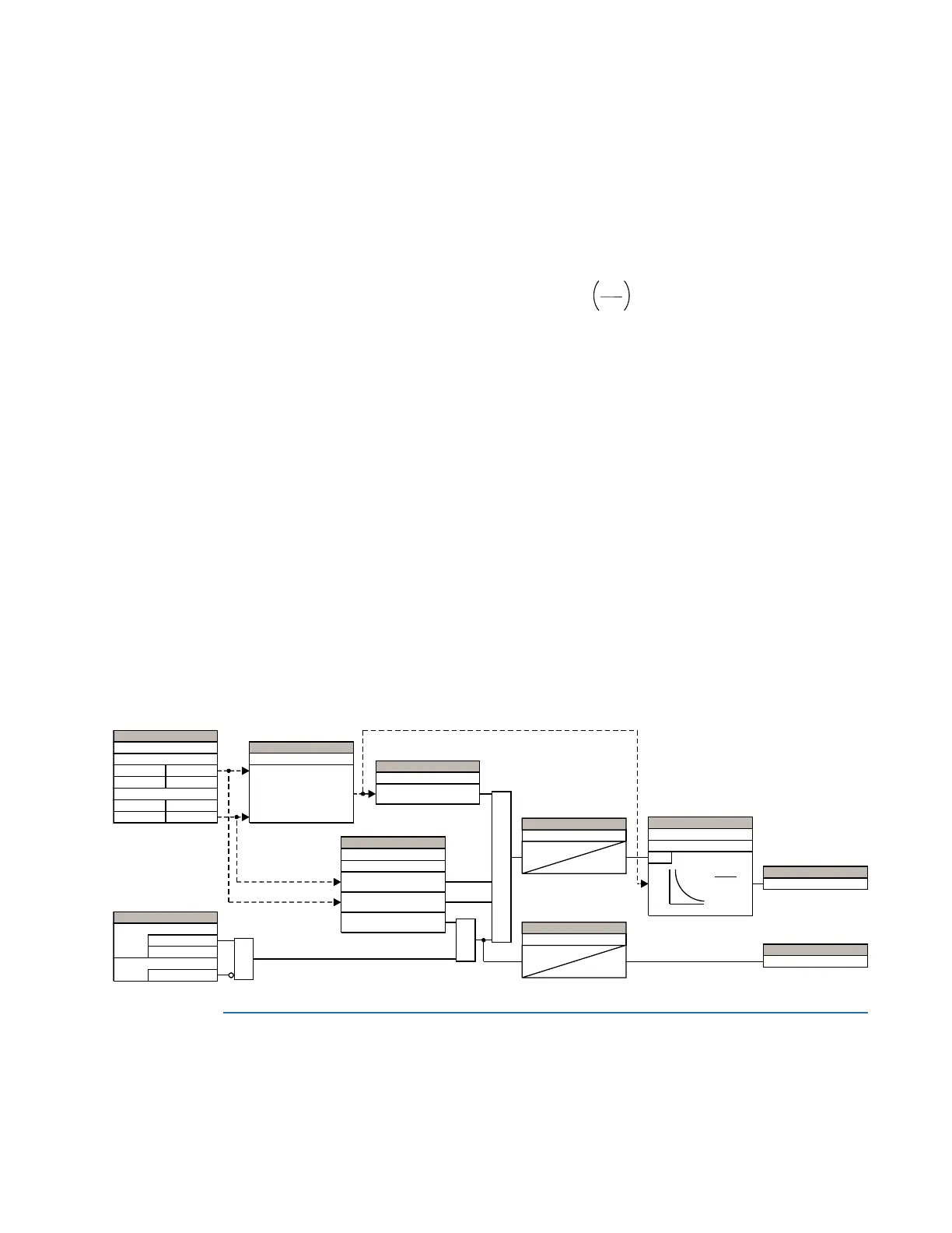
The figure shows the logic for the wattmetric zero-sequence directional ground fault 1
element. The logic is identical for both wattmetric elements.
Figure 251: Wattmetric zero-sequence directional ground fault logic
Control elements
Control elements generally are used for control rather than protection.
$&'5
6(77,1*6
&DOFXODWHG
1HXWUDO,Q
6RXUFH
&XUUHQW
0HDVXUHG
*URXQG,J
&DOFXODWHG
1HXWUDO9Q
9ROWDJH
0HDVXUHG
$X[LOLDU\9[
6(77,1*
(&$
6 îFRQM îH 9,
² î(&$M
6(77,1*
3RZHU3LFNXS
6BRS!3RZHU3LFNXS
9BPDJ!2&3LFNXS
6(77,1*6
293LFNXS
2&3LFNXS
,BPDJ!293LFNXS
6(77,1*
(QDEOHG
'LVDEOHG
)XQFWLRQ
2II
%ORFN
$1'
$1'
$1'
6(77,1*
2&3LFNXS'HOD\
7
SLFNXS
6(77,1*
3RZHU3LFNXS'HOD\
7
SLFNXS
6(77,1*
&XUYH
0XOWLSOLHU
581
W Pî
6BUHI
6BRS
)/(;/2*,&23(5$1'
:$770(75,&23
)/(;/2*,&23(5$1'
:$770(75,&3.3
6BRS!3RZHU3LFNXS