CHAPTER 7: PROTECTION PROTECTION INPUTS AND OUTPUTS
D90
PLUS
LINE DISTANCE PROTECTION SYSTEM – INSTRUCTION MANUAL 399
The following setting is available for all 16 teleprotection inputs on channels 1 and 2.
Teleprotection Input 1 Default States
Range: Off, On, Latest/Off, Latest/On
Default: Off
Programming this setting to “On” defaults the input to logic 1 when the channel fails. A
value of “Off” defaults the input to logic 0 when the channel fails.
The “Latest/On” and “Latest/Off” values freeze the input in case of lost communication. If
the latest state is not known, such as after relay power-up but before the first
communication exchange, then the input defaults to logic 1 for “Latest/On” and logic 0
for “Latest/Off.”
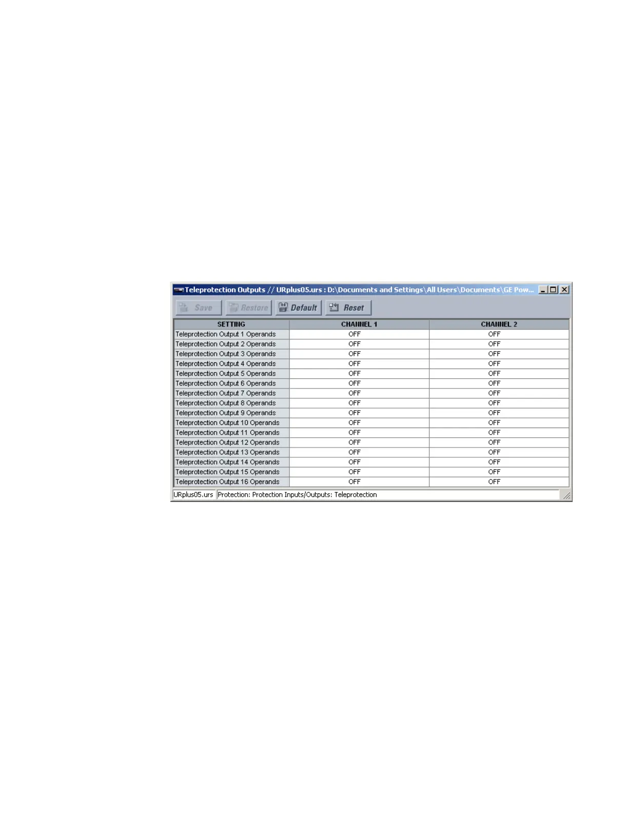
Teleprotection output settings
Select the Settings > Protection > Protection Inputs/Outputs > Teleprotection >
Teleprotection Outputs menu to open the teleprotection outputs configuration window.
Figure 343: Teleprotection outputs configuration settings
The following setting is available for all 16 teleprotection inputs on channels 1 and 2.
Teleprotection Output 1 Operands
Range: any FlexLogic operand
Default: Off
Processing of the teleprotection inputs and outputs is dependent on the number of
communication channels and terminals. On two-terminal two-channel systems, they
are processed continuously on each channel and mapped separately per channel.
Therefore, to achieve redundancy, the user must assign the same operand on both
channels (teleprotection outputs at the sending end or corresponding teleprotection
inputs at the receiving end). On three-terminal two-channel systems, redundancy is
achieved by programming signal re-transmittal in the case of channel failure between
any pair of UR
Plus
-series devices.
Teleprotection input actual values
Select the Actual Values > Protection > Protection Inputs/Outputs > Teleprotection
Inputs menu to open the teleprotection inputs states window.