CHAPTER 6: COMMUNICATIONS IEC 61850 COMMUNICATIONS
D90
PLUS
LINE DISTANCE PROTECTION SYSTEM – INSTRUCTION MANUAL 133
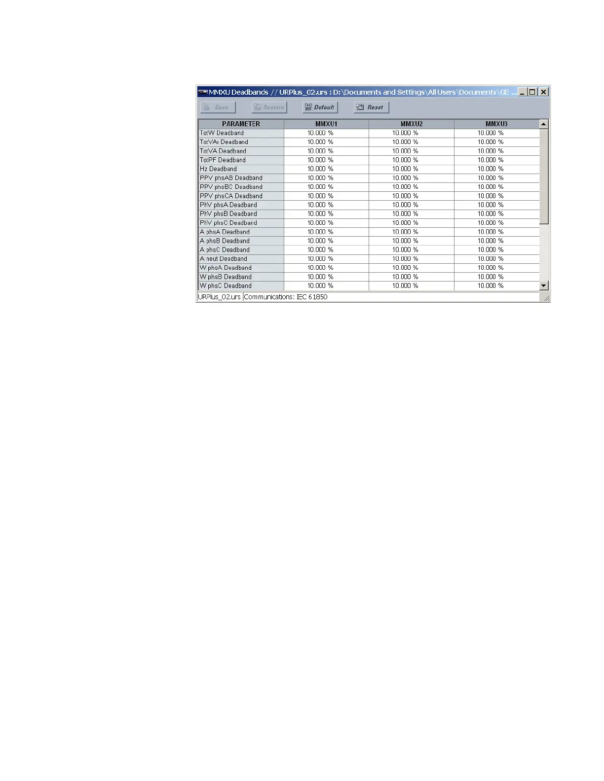
Figure 106: IEC 61850 MMXU deadband configuration settings
The following settings are available for each of the four MMXU nodes.
Total Watt Deadband
Range: 0.001 to 100.000% in steps of 0.001
Default: 10.000%
This setting specifies the real power deadband value. The maximum value representing
100% of deadband is 46 × phase CT secondary × phase CT ratio × 275 × VT ratio.
Total Var Deadband
Range: 0.001 to 100.000% in steps of 0.001
Default: 10.000%
This setting specifies the reactive power deadband value. The maximum value
representing 100% of deadband is 46 × phase CT secondary × phase CT ratio × 275 × VT
ratio.
Total VA Deadband
Range: 0.001 to 100.000% in steps of 0.001
Default: 10.000%
This setting specifies the apparent power deadband value. The 100% deadband value is
46 × phase CT secondary × phase CT ratio × 275 × VT ratio.
Total Power Factor Deadband
Range: 0.001 to 100.000% in steps of 0.001
Default: 10.000%
This setting specifies the power factor deadband value. The 100% deadband value is 2.
Hz Deadband
Range: 0.001 to 100.000% in steps of 0.001
Default: 10.000%
This setting specifies the frequency deadband value. The 100% deadband value is 90 Hz.
PPV Phase AB Deadband, PPV Phase BC Deadband, PPV Phase CA Deadband
Range: 0.001 to 100.000% in steps of 0.001
Default: 10.000%
These settings specify the Vab, Vbc, and Vca per-phase voltage deadband values. The
100% deadband value is 275 × VT ratio.