CHAPTER 7: PROTECTION POWER SYSTEM
D90
PLUS
LINE DISTANCE PROTECTION SYSTEM – INSTRUCTION MANUAL 175
For three-phase channel groups, the number of the lowest numbered channel identifies
the group. For example, J1 represents the three-phase channel set of J1, J2, and J3, where
J is the slot letter and 1 is the first channel of the set of three channels. The first channel in
the group is identified as phase A, the second channel as phase B, and the third channel as
phase C.
Current inputs
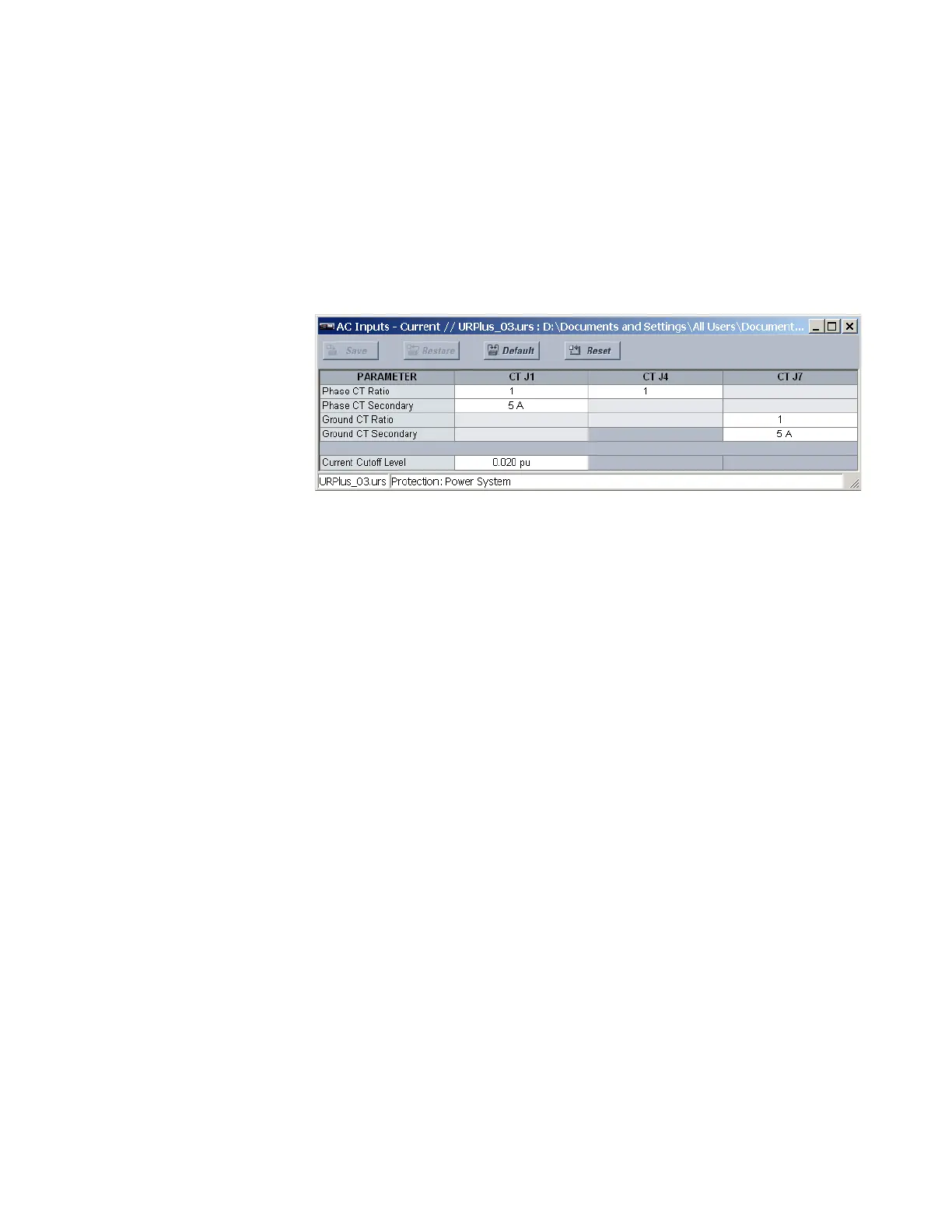
Select the Settings > Protection > Power System > AC Inputs - Current menu to open the
current inputs configuration window.
Figure 155: Current inputs configuration settings
The current inputs window sets the parameters for each current input (represented by the
module slot position letter). The
Phase CT Ratio and Ground CT Ratio settings are used for
calculation of primary metering values and for ratio matching when multiple CT inputs are
added within a source. The
Phase CT Secondary and Ground CT Secondary settings are
used to derive secondary current values from per-unit settings used in protection
elements. This setting is “1 A” or “5 A,” depending on the hardware.
Since the phase CTs are connected in a wye (star) configuration, the calculated phasor
sum of the three phase currents (IA + IB + IC = neutral current = 3I0) is used as the input for
the neutral overcurrent elements. In addition, a zero-sequence (core-balance) CT that
senses current in all of the circuit primary conductors, or a CT in a neutral grounding
conductor, can be used.
The following current input settings are available.
Phase CT Ratio
Range: 1 to 65000 in steps of 1
Default: 1
This setting specifies the phase CT ratio for the corresponding current input. It is used for
calculation of primary metering values and for ratio matching when multiple CT inputs
are added within a source.
Phase CT Secondary
Range: 1 A, 5 A
Default: 5 A
This setting selects the phase CT secondary value. It is used to derive secondary current
values from per-unit settings used in protection elements.
Ground CT Ratio
Range: 1 to 65000 in steps of 1
Default: 1
This setting specifies the ground CT ratio for the corresponding current input. It is used
for calculation of primary metering values and for ratio matching when multiple CT
inputs are added within a source.