236 D90
PLUS
LINE DISTANCE PROTECTION SYSTEM – INSTRUCTION MANUAL
GROUPED PROTECTION ELEMENTS CHAPTER 7: PROTECTION
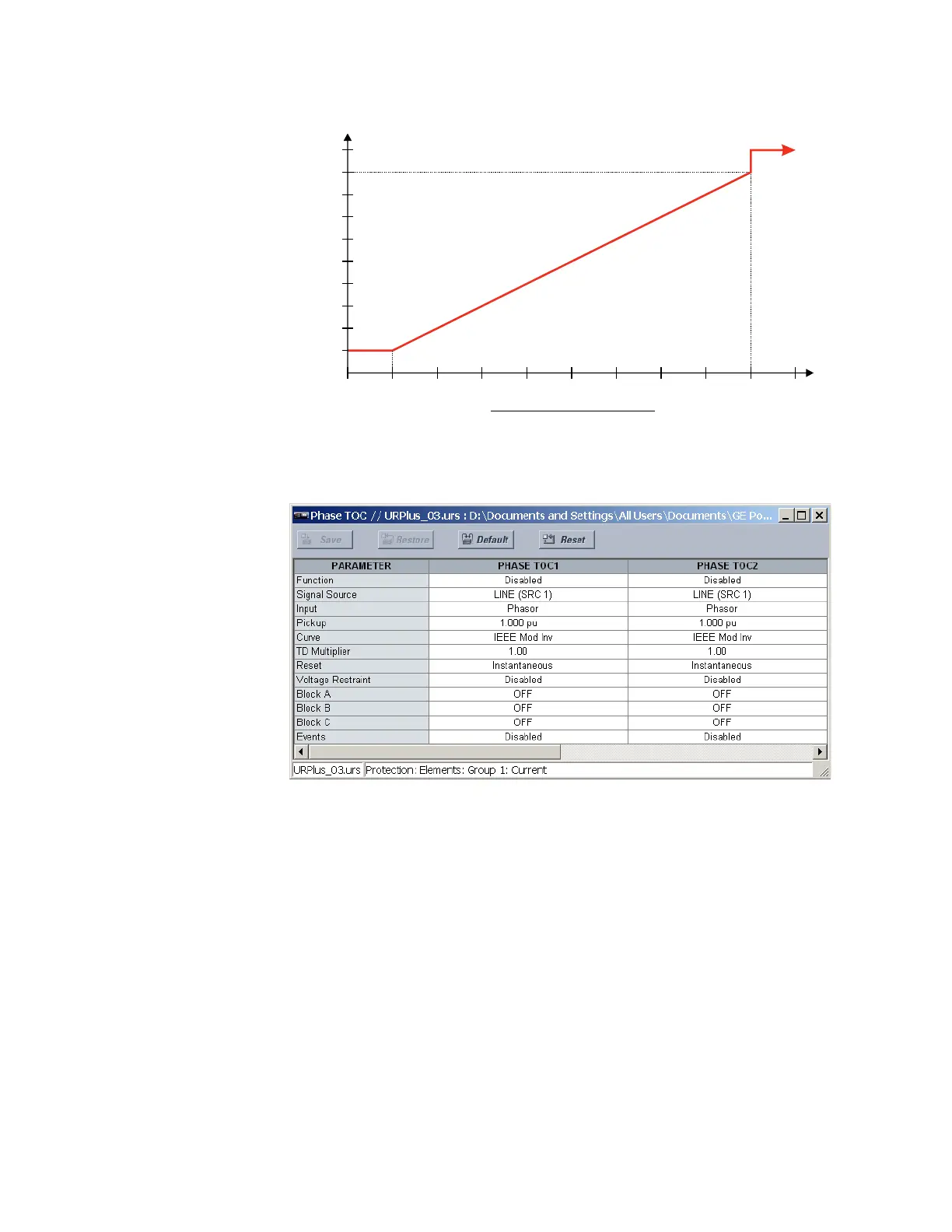
Figure 201: Phase time overcurrent voltage restraint characteristic
Select the Settings > Protection > Elements > Group 1 > Current > Phase TOC menu item
to open the phase time overcurrent configuration window.
Figure 202: Phase time overcurrent configuration settings
The following settings are available for each phase time overcurrent element.
Function
Range: Enabled, Disabled
Default: Disabled
This setting enables and disables the phase time overcurrent protection element.
Signal Source
Range: LINE (SRC 1), BKR 1 (SRC 2), BKR 2 (SRC 3)
Default: LINE (SRC 1)
This setting selects the signal source for the phase time overcurrent protection element.
Input
Range: Phasor, RMS
Default: Phasor
This setting selects how phase current input quantities are interpreted by the D90
Plus
.
Inputs can be selected as fundamental phasor magnitudes or total waveform RMS
magnitudes as required by the application.
$&'5
3LFNXSFXUUHQWPXOWLSOLHU
3KDVHWRSKDVHYROWDJH
97QRPLQDOSKDVHWRSKDVHYROWDJH