CHAPTER 7: PROTECTION GROUPED PROTECTION ELEMENTS
D90
PLUS
LINE DISTANCE PROTECTION SYSTEM – INSTRUCTION MANUAL 275
Auxiliary overvoltage
This element is intended for monitoring overvoltage conditions of the auxiliary voltage. A
typical application for this element is monitoring the zero-sequence voltage (3V_0)
supplied from an open-corner-delta VT connection. The nominal secondary voltage of the
auxiliary voltage channel entered in the
Auxiliary VT Secondary setting is the per-unit base
used when setting the pickup level.
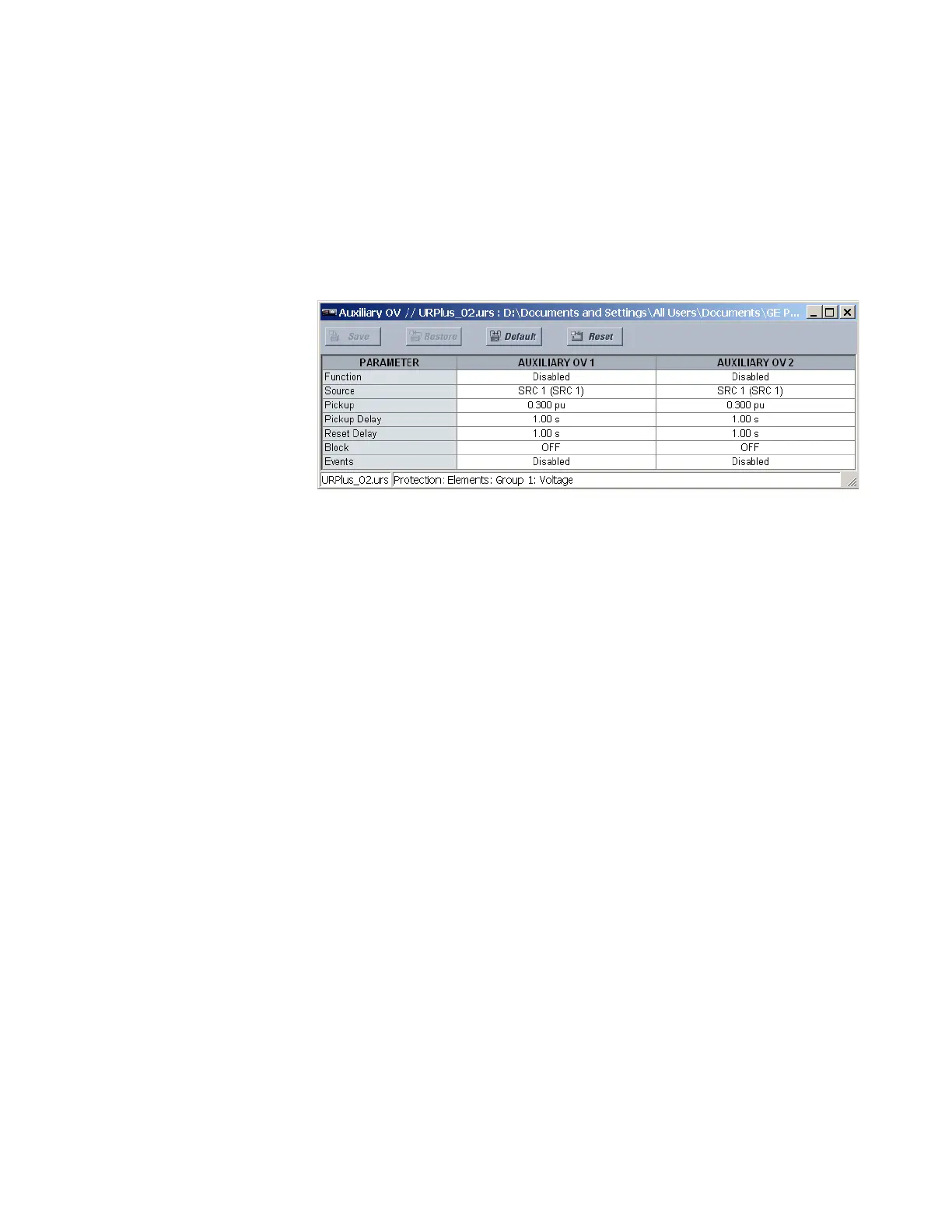
Select the Settings > Protection > Elements > Group 1 > Voltage > Auxiliary OV menu to
open the auxiliary overvoltage configuration window.
Figure 238: Auxiliary overvoltage configuration settings
The following settings are available for each auxiliary overvoltage element.
Function
Range: Enabled, Disabled
Default: Disabled
This setting enables and disables the auxiliary overvoltage protection element.
Source
Range: LINE (SRC 1), BKR 1 (SRC 2), BKR 2 (SRC 3)
Default: LINE (SRC 1)
This setting selects the signal source for the auxiliary overvoltage protection element.
Pickup
Range: 0.000 to 1.100 pu in steps of 0.001
Default: 0.300 pu
This setting specifies the auxiliary overvoltage pickup level in per-unit values.
Pickup Delay
Range: 0.00 to 600.00 seconds in steps of 0.01
Default: 1.00 seconds
This setting selects the minimum operating time of the auxiliary overvoltage element.
Reset Delay
Range: 0.00 to 600.00 seconds in steps of 0.01
Default: 1.00 seconds
This setting specifies the minimum reset time of the auxiliary overvoltage element.
Block
Range: any FlexLogic operand or shared operand
Default: Off
Assertion of the operand assigned to this setting blocks the auxiliary overvoltage
element.