326 D90
PLUS
LINE DISTANCE PROTECTION SYSTEM – INSTRUCTION MANUAL
CONTROL ELEMENTS CHAPTER 7: PROTECTION
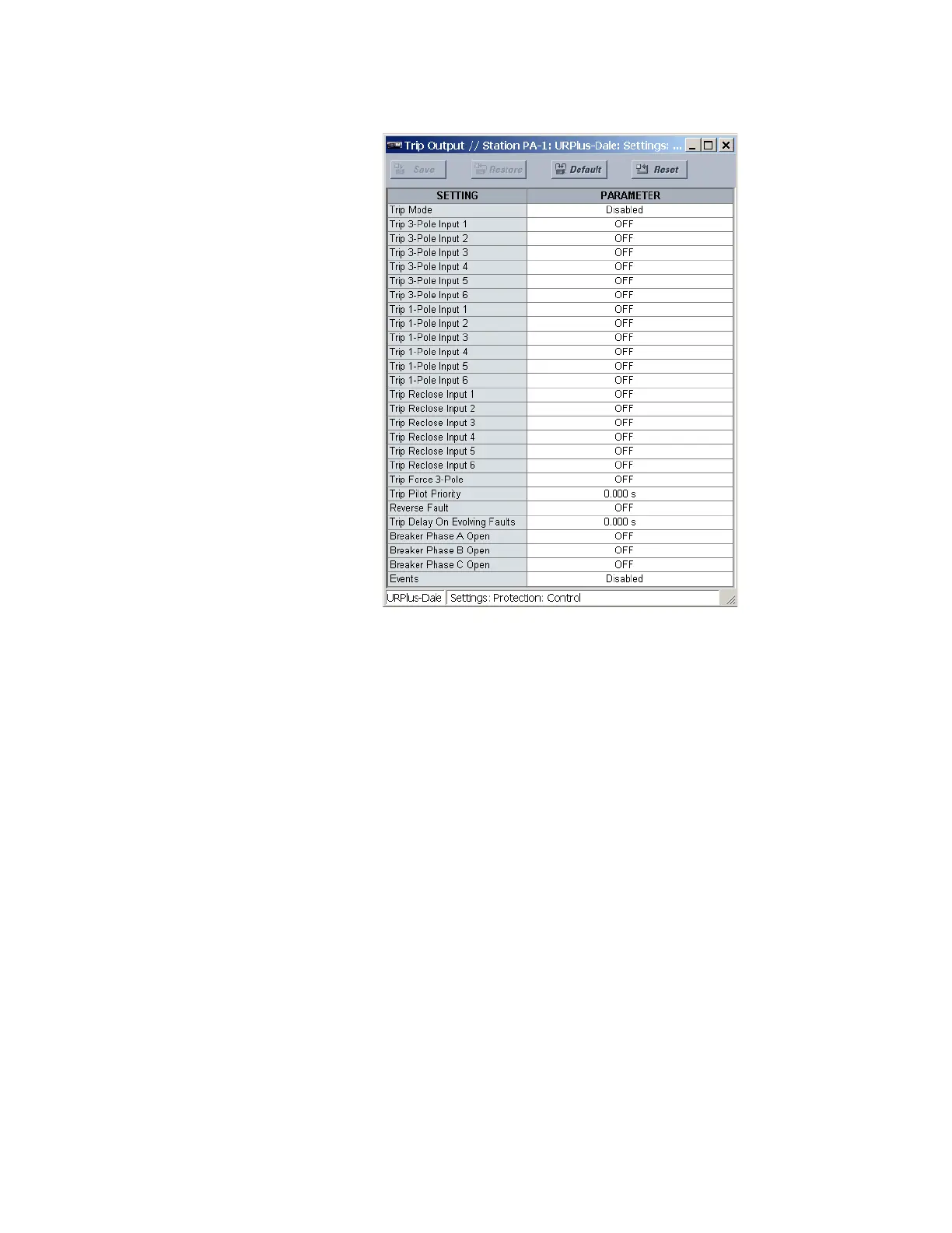
Figure 267: Trip output configuration settings
The following settings are available.
Trip Mode
Range: Disabled, 3 Pole Only, 3 Pole & 1 Pole
Default: Disabled
This setting selects the required mode of operation. If selected to “3 Pole Only,” outputs
for all three phases are always set simultaneously. If selected to “3 Pole & 1 Pole,”
outputs for all three phases are set simultaneously unless the phase selector or a pilot
aided scheme determines the fault is single-phase-to-ground. If the fault is identified as
being AG, BG, or CG only the operands for the faulted phase are asserted.
Trip 3-Pole Input 1, Trip 3-Pole Input 2, Trip 3-Pole Input 3, Trip 3-Pole Input 4, Trip 3-
Pole Input 5, Trip 3-Pole Input 6
Range: any FlexLogic operand
Default: OFF
These settings select an operand representing an unwanted fault condition to initiate a
single pole operation (for example, phase undervoltage). A FlexLogic OR-gate can be
used if more than six inputs are required.
Trip 1-Pole Input 1, Trip 1-Pole Input 2, Trip 1-Pole Input 3, Trip 1-Pole Input 4, Trip 1-
Pole Input 5, Trip 1-Pole Input 6
Range: any FlexLogic operand
Default: OFF
These settings select an operand representing a fault condition that is required to initiate
a single pole trip-and-reclose if the fault is single phase to ground (for example, phase
distance zone 1). Use a FlexLogic OR-gate if more than six inputs are required. The inputs
do not have to be phase-specific, as the phase selector determines the fault type.