CHAPTER 7: PROTECTION CONTROL ELEMENTS
D90
PLUS
LINE DISTANCE PROTECTION SYSTEM – INSTRUCTION MANUAL 373
Breaker flashover settings
Select the Settings > Protection > Control > Breaker Flashover menu to open the breaker
flashover configuration window.
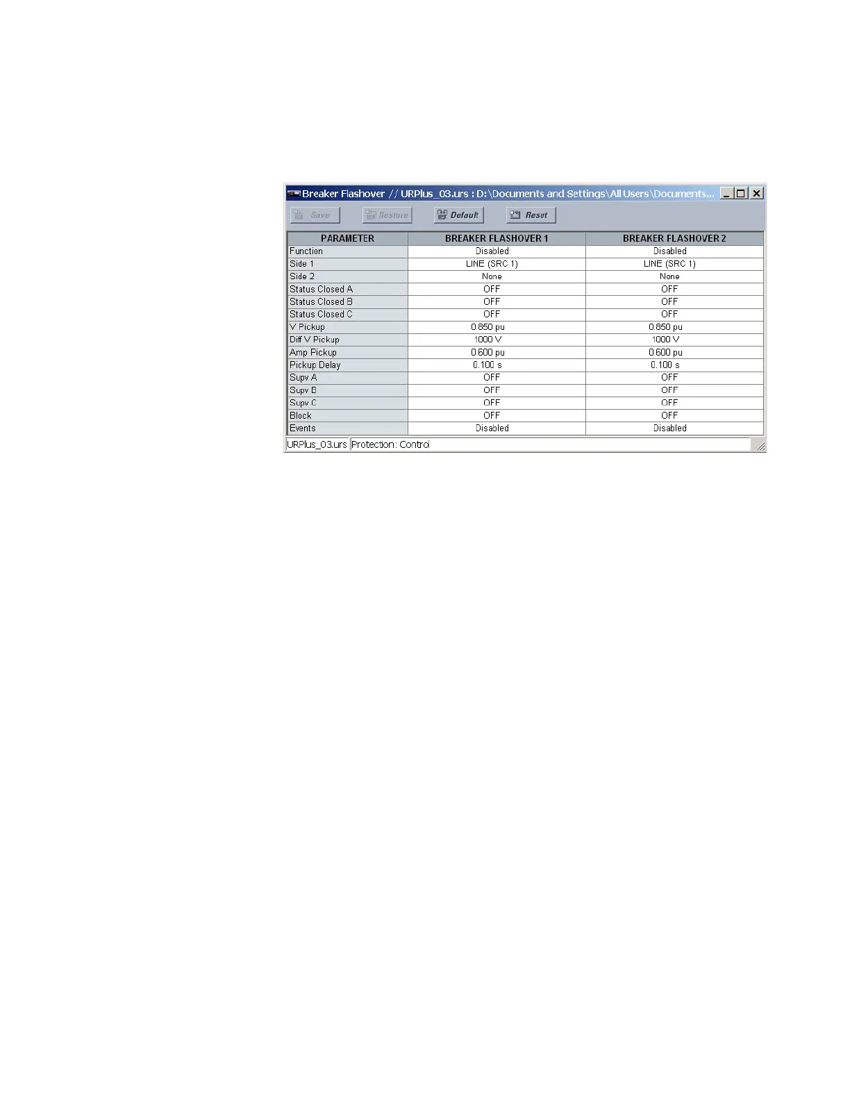
Figure 312: Breaker flashover configuration settings
The following settings are available for each breaker flashover element.
Function
Range: Enabled, Disabled
Default: Disabled
This setting enables and disables the breaker flashover protection element.
Side 1
Range: LINE (SRC 1), BKR 1 (SRC 2), BKR 2 (SRC 3)
Default: LINE (SRC 1)
This setting specifies a signal source used to provide three-phase voltages and three-
phase currents from one side of the current breaker. The source is selected by this
setting and must be configured with breaker phase voltages and currents, even if only
three VTs are available across the breaker.
Side 2
Range: None, LINE (SRC 1), BKR 1 (SRC 2), BKR 2 (SRC 3)
Default: varies with UR
Plus
-series model; see the EnerVista UR
Plus
Setup software
This setting specifies a signal source used to provide another set of three-phase
voltages whenever six VTs are available across the breaker.
Status Closed A, Status Closed B, Status Closed C
Range: any FlexLogic operand or shared operand
Default: BKR1 CLOSED
These settings specify operands to indicate the open status of the breaker. A separate
operand can be selected to detect individual breaker pole status and provide flashover
detection. The recommended setting is 52a breaker contact or another operand
defining the breaker poles open status.