390 D90
PLUS
LINE DISTANCE PROTECTION SYSTEM – INSTRUCTION MANUAL
PROTECTION INPUTS AND OUTPUTS CHAPTER 7: PROTECTION
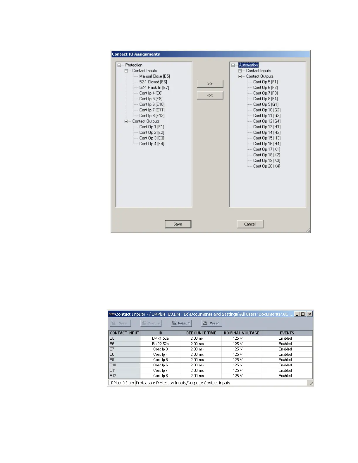
Figure 330: Contact input and output assignments
All available contact inputs and outputs can be reassigned using the >> and << buttons.
Contact input settings
When the input detects a voltage decrease, the input circuitry draws 10 mA of current. If
the voltage decrease is due to a state change then the voltage quickly decreases,
speeding up the recognition of the reset of the field contact.
Select the Settings > Protection > Protection Inputs/Outputs > Contact Inputs > Contact
Inputs menu to access the contact input configuration settings.
Figure 331: Contact input configuration settings
The contact inputs menu contains configuration settings for each contact input. Upon
startup, the relay processor determines (from an assessment of the installed modules)
which contact inputs are available and then displays settings for only those inputs. The
following settings are available for each contact input.