CHAPTER 7: PROTECTION PROTECTION FLEXLOGIC
D90
PLUS
LINE DISTANCE PROTECTION SYSTEM – INSTRUCTION MANUAL 403
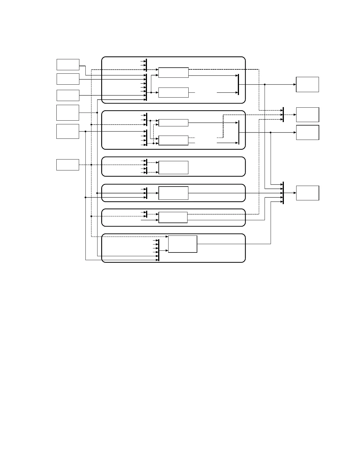
Figure 347: UR
Plus
-series architecture overview
The states of all digital signals used in the D90
Plus
are represented by flags (or FlexLogic
operands, which are described later in this section). A logic 1 state is represented by a set
flag. Any external contact change-of-state can be used to block an element from
operating, as an input to a control feature in a FlexLogic equation, or to operate a contact
output. The state of the contact input can be displayed locally or viewed remotely via the
communications facilities provided. If a simple scheme where a contact input is used to
block an element is desired, this selection is made when programming the element. This
capability also applies to the other features that set flags: elements, virtual inputs, remote
inputs, schemes, and human operators.
If more complex logic is required, it is implemented via FlexLogic. For example, to have the
closed state of contact input H7a and the operated state of the phase undervoltage
element block the operation of the phase time overcurrent element, the two control input
states are programmed in a FlexLogic equation. This equation ANDs the two control inputs
to produce a virtual output, which is then selected when programming the phase time
overcurrent to be used as a blocking input. Virtual outputs can only be created by
FlexLogic equations.
Traditionally, protective relay logic has been relatively limited. Any unusual applications
involving interlocks, blocking, or supervisory functions had to be hard-wired using contact
inputs and outputs. FlexLogic minimizes the requirement for auxiliary components and
wiring while making more complex schemes possible.
Virtual outputs
Elements…
FlexLogic
Virtual analogs
Data logger,
synchrophasors
Protection
Protection analog values
FlexAnalog values
Protection operands
Virtual inputs
Shared operands
Automation
Virtual analog values
FlexAnalog values
Elements…
Automation logic
Automation operands
Virtual inputs
Shared operands
Digital fault recorder
FlexAnalog values
Equipment manager
Shared operands
Metering
Front panel HMI
Remote
inputs
Automation
contact
inputs
Protection
contact
inputs
CTs and VTs
DSP
Automation
contact
outputs
870701A3.CDR
FlexAnalogs
Virtual outputs
Protection operands
Shared operands
Transient record,
Disturbance record,
Fault report
Battery monitor
Breaker arcing
FlexAnalog values
Shared operands
Protection operands
Automation operands
Metering operands
Equipment manager operands
Annunciator,
Mimic diagram
Shared
operands
Protection
contact
outputs
Teleprotection
inputs
Direct
inputs