CHAPTER 9: EQUIPMENT MANAGER CIRCUIT BREAKER ARCING MANAGEMENT
D90
PLUS
LINE DISTANCE PROTECTION SYSTEM – INSTRUCTION MANUAL 495
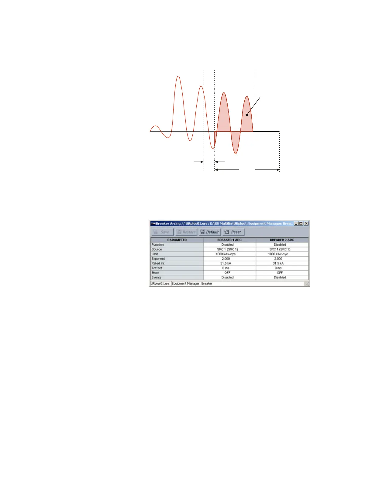
Figure 429: Breaker arcing current measurement
Select the Settings > Equipment Manager > Breaker > Breaker Arcing menu to open the
breaker arcing current configuration window.
Figure 430: Breaker arcing current configuration settings
The following settings are available for each breaker arcing current element.
Function
Range: Enabled, Disabled
Default: Disabled
This settings enables or disables the breaker arcing current function.
Source
Range: LINE (SRC 1), BKR 1 (SRC 2), BKR 2 (SRC 3)
Default: LINE (SRC 1)
This setting selects the signal source for the breaker arcing current element.
Limit
Range: 0 to 50000 kA
2
-cycle in steps of 1
Default: 1000 kA
2
-cycle
This setting specifies the limit of the accumulated current arcing time for maintenance.
%UHDNHU
FRQWDFWV
SDUW
$UF
H[WLQJXLVKHG
PV
6WDUW
LQWHJUDWLRQ
6WRS
LQWHJUDWLRQ
7RWDO$UHD EUHDNHUDUFLQJ
FXUUHQWN$
F\FOH
$&'5
D
GURSRXW
2IIVHW7LPH