510 D90
PLUS
LINE DISTANCE PROTECTION SYSTEM – INSTRUCTION MANUAL
FAULT REPORT CHAPTER 10: DIGITAL FAULT RECORDER
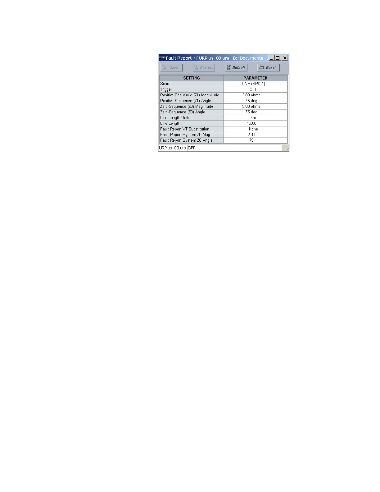
Figure 442: Fault report configuration settings
The following settings are available.
Source
Range: LINE (SRC 1), BKR 1 (SRC 2), BKR 2 (SRC 3)
Default: SRC1
This setting selects the source for input currents, voltages, and disturbance detection.
Trigger
Range: any FlexLogic operand
Default: OFF
This setting assigns the FlexLogic operand representing the protection elements
requiring operational fault location calculations. The distance to fault calculations are
initiated by this signal.
Positive-Sequence (Z1) Magnitude
Range: 0.01 to 250.00 ohms in steps of 0.01
Default: 3.00 ohms
This setting specifies the magnitude of positive-sequence impedance of the
transmission line or feeder in secondary ohms.
Positive-Sequence (Z1) Angle
Range: 25 to 90° in steps of 1
Default: 75°
This setting specifies the angle of positive-sequence impedance of the transmission line
or feeder in secondary ohms.
Zero-Sequence (Z0) Magnitude
Range: 0.01 to 650.00 ohms in steps of 0.01
Default: 9.00 ohms
This setting specifies the magnitude of zero-sequence impedance of the transmission
line or feeder in secondary ohms.
Zero-Sequence (Z0) Angle
Range: 25 to 90° in steps of 1
Default: 75°
This setting specifies the angle of zero-sequence impedance of the transmission line or
feeder in secondary ohms.