518 D90
PLUS
LINE DISTANCE PROTECTION SYSTEM – INSTRUCTION MANUAL
TRANSIENT RECORDER CHAPTER 10: DIGITAL FAULT RECORDER
Signals
Range: any FlexLogic operand or shared operand
Default: OFF
This setting specifies an operand to use as a transient recorder digital channel. The pull-
down list of available signals is populated with enabled protection functions. Selected
operands are assigned automatically as channels and as triggers according to their
importance and can be de-assigned by the user.
For example, when ground time overcurrent 1 has been enabled, the following
assignments are made from the list of available operands.
Table 37: Ground time overcurrent 1 signal example
Trigger
Range: Off, Trigger Only, Trigger/Re-Trigger, Re-Trigger Only
Default: Off
This setting selects the trigger function of the digital channel. When set to “Trigger Only”
or “Trigger/Re-Trigger,” the transient recorder initiates data capture for an OFF-ON
transition of the channel signal. The resulting record contains both pre-fault and fault
data and the channel must return to the off state before it can generate a subsequent
trigger.
When set to “Trigger/Re-Trigger” or “Re-Trigger Only,” the transient recorder is re-
triggered if the signal is still asserted at the end of the trigger period. The resulting record
contains fault data only. A re-trigger is re-generated at the end of a transient record if
the signal is still asserted and if the number of re-triggers is less than the value specified
by the
Maximum Re-Triggers setting.
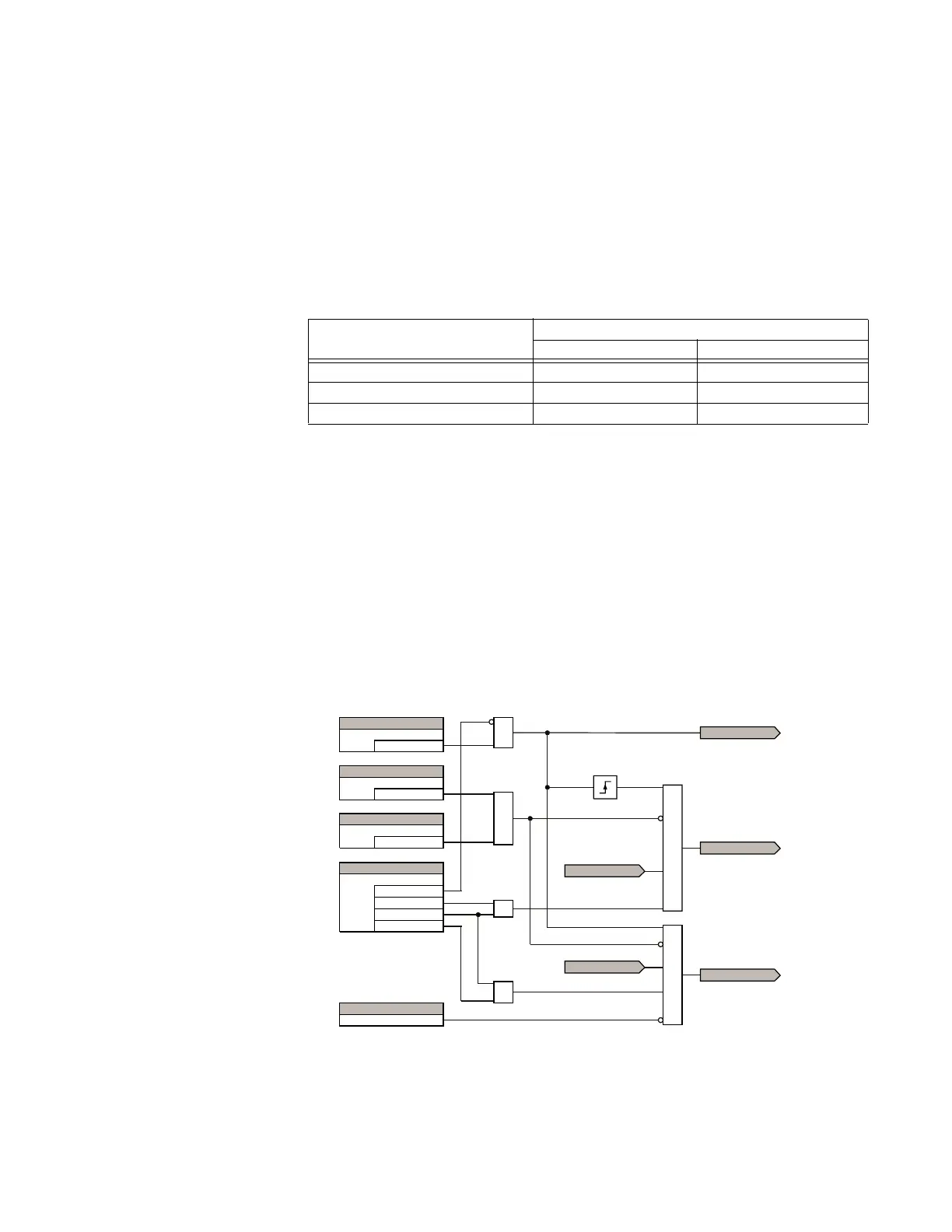
Figure 450: Digital channel triggering logic
Available signals (operands) Operand assigned as a...
Digital channel Trigger
GND TOC1 DPO Yes No
GND TOC1 OP Yes Yes
GND TOC1 PKP Yes No
$&'5
25
6(77,1*
2II
6LJQDO
6(77,1*
'LVDEOHG
)XQFWLRQ
6(77,1*
2II
%ORFN7ULJJHU
6(77,1*
2II
7ULJJHU
7ULJJHU2QO\
7ULJJHU5H7ULJJHU
5H7ULJJHU2QO\
25
$1'
25
75,**(56839
$1'
',*&+75,**(5
',*&+$&7,9(
5(75,**(56839
$1'
',*&+5(75,**(5
)/(;/2*,&23(5$1'
5(75,**(56 0$;