526 D90
PLUS
LINE DISTANCE PROTECTION SYSTEM – INSTRUCTION MANUAL
DISTURBANCE RECORDER CHAPTER 10: DIGITAL FAULT RECORDER
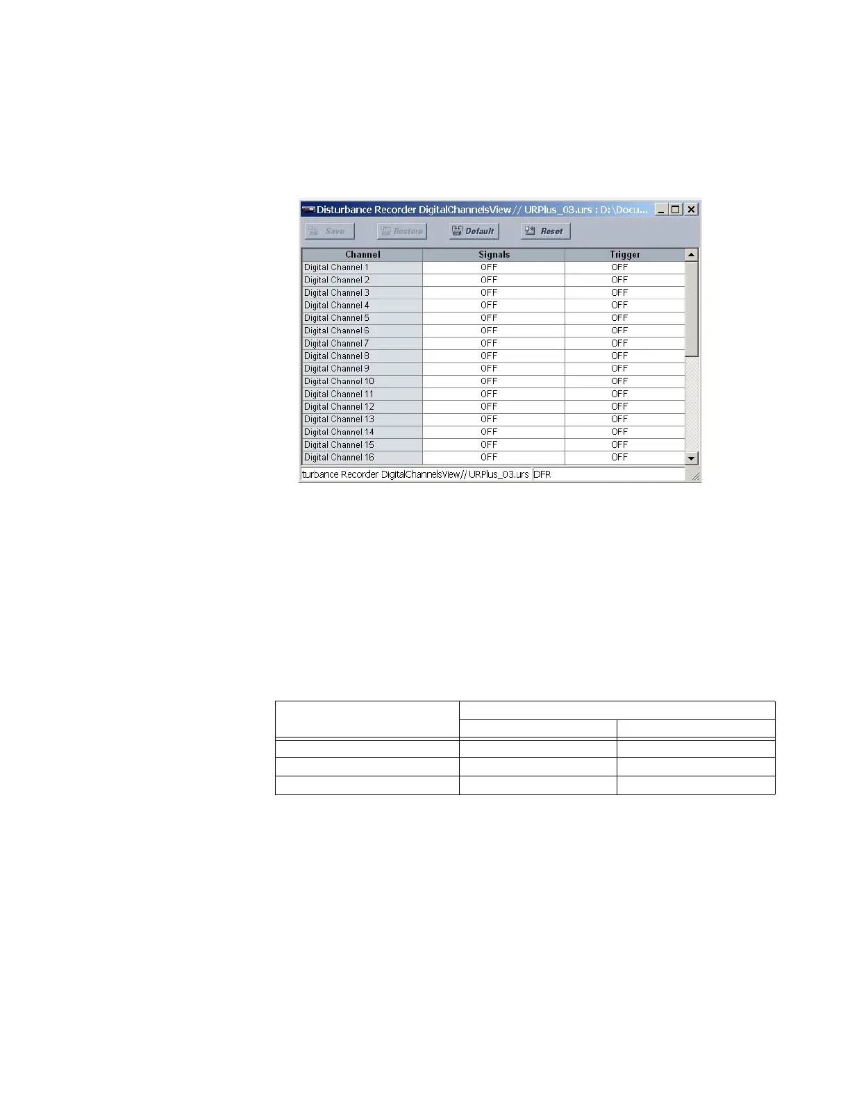
Disturbance recorder digital channels
Up to 32 digital channels can be assigned to the disturbance recorder. Each channel can
be configured individually by clicking the digital channels Select button in the disturbance
recorder window to open the disturbance recorder digital channels window.
Figure 458: Digital channel configuration settings
The following settings are available for each disturbance recorder digital channel.
Signals
Range: any FlexLogic operand or shared operand
Default: Off
This setting selects an operand to act as a trigger for the digital channel.
The pull-down list of available signals is populated according to the protection functions
that have been enabled. Selected signals are assigned automatically as channels and as
triggers according to their importance. These signals can be deactivated by the user. For
example, if ground time overcurrent 1 has been enabled, then the following assignments
are made.
Table 39: Example disturbance recorder signal assignment
Trigger
Range: Off, Trigger Only, Trigger/Re-Trigger, Re-Trigger Only
Default: Off
This setting selects the trigger function of the digital channel. When set to “Trigger Only”
or “Trigger/Re-Trigger,” the disturbance recorder initiates data capture for an OFF-ON
transition of the channel signal. The resulting record contains both pre-fault and fault
data and the channel must return to the off state before it can generate a subsequent
trigger.
Available signals Assignment
Digital channel Trigger
GND TOC1 DPO Yes No
GND TOC1 OP Yes Yes
GND TOC1 PKP Yes No