CHAPTER 11: METERING PHASOR MEASUREMENT UNIT
D90
PLUS
LINE DISTANCE PROTECTION SYSTEM – INSTRUCTION MANUAL 543
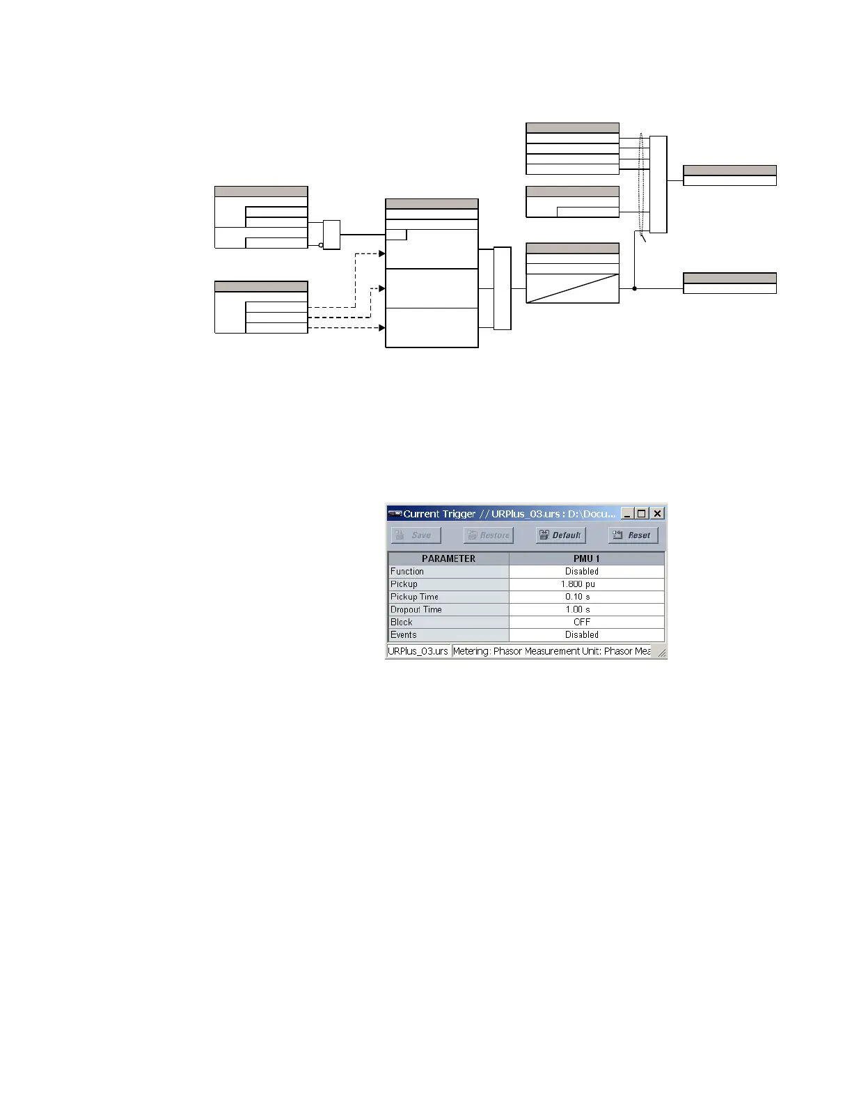
Figure 473: Voltage triggering logic
Current triggering
This Phasor Measurement Unit current triggering responds to elevated current. The trigger
responds to the phase current signal of the PMU source. All current channel (A, B, and C)
are processed independently and can trigger the recorder.
Select the Settings > Metering > Phasor Measurement Unit > Triggering > Current
Trigger menu to open the PMU current triggering window.
Figure 474: Current triggering configuration settings
The following settings are available for each PMU.
Function
Range: Enabled, Disabled
Default: Disabled
This setting enables and disables the PMU current triggering function.
Pickup
Range: 0.100 to 30.000 pu in steps of 0.001
Default: 1.800 pu
This setting specifies the pickup threshold for the overcurrent trigger, in per-unit values
of the PMU source. A value of 1 pu is a nominal primary current. The comparator applies
a 3% hysteresis.
Pickup Time
Range: 0.00 to 600.00 seconds in steps of 0.01
Default: 0.10 seconds
This setting is used to filter out spurious conditions and avoid unnecessary triggering of
the recorder.
$&'5
6(77,1*6
'LVDEOHG
(QDEOHG
)XQFWLRQ
2II
%ORFN
$1'
6(77,1*
9$RU9$%
9%RU9%&
6LJQDO6RXUFH
9&RU9&$
6(77,1*6
+LJK9ROWDJH
581
SX9/RZ9ROWDJH
RU
9!+LJK9ROWDJH
/RZ9ROWDJH
SX9/RZ9ROWDJH
RU
9!+LJK9ROWDJH
SX9/RZ9ROWDJH
RU
9!+LJK9ROWDJH
25
6(77,1*
3LFNXS7LPH
7
3.3
7
'32
'URSRXW7LPH
WR67$7ELWVRIWKHGDWDIUDPH
)/(;/2*,&23(5$1'6
308)5(475,**(5
308&85575,**(5
30832:(575,**(5
30852&2)75,**(5
6(77,1*
2II
8VHU7ULJJHU
25
)/(;/2*,&23(5$1'
30875,**(5('
)/(;/2*,&23(5$1'
30892/775,**(5