562 D90
PLUS
LINE DISTANCE PROTECTION SYSTEM – INSTRUCTION MANUAL
METERED VALUES CHAPTER 11: METERING
For display and oscillography purposes, all phasor angles in a given device are referred to
an AC input channel pre-selected by the
Frequency and Phase Reference setting in the
Settings > Protection > Power System > Frequency menu. This setting defines a
particular AC signal source to be used as the reference.
The D90
Plus
first determines if any phase VT bank is indicated in the source. If it is, voltage
channel VA of that bank is used as the angle reference. Otherwise, the D90
Plus
determines
if any auxiliary VT bank is indicated. If it is, the auxiliary voltage channel of that bank is
used as the angle reference. If neither of these two conditions are satisfied, then two more
steps of this hierarchical procedure to determine the reference signal include the phase CT
bank and the ground CT bank.
If the AC signal pre-selected by the D90
Plus
upon configuration is not measurable, then the
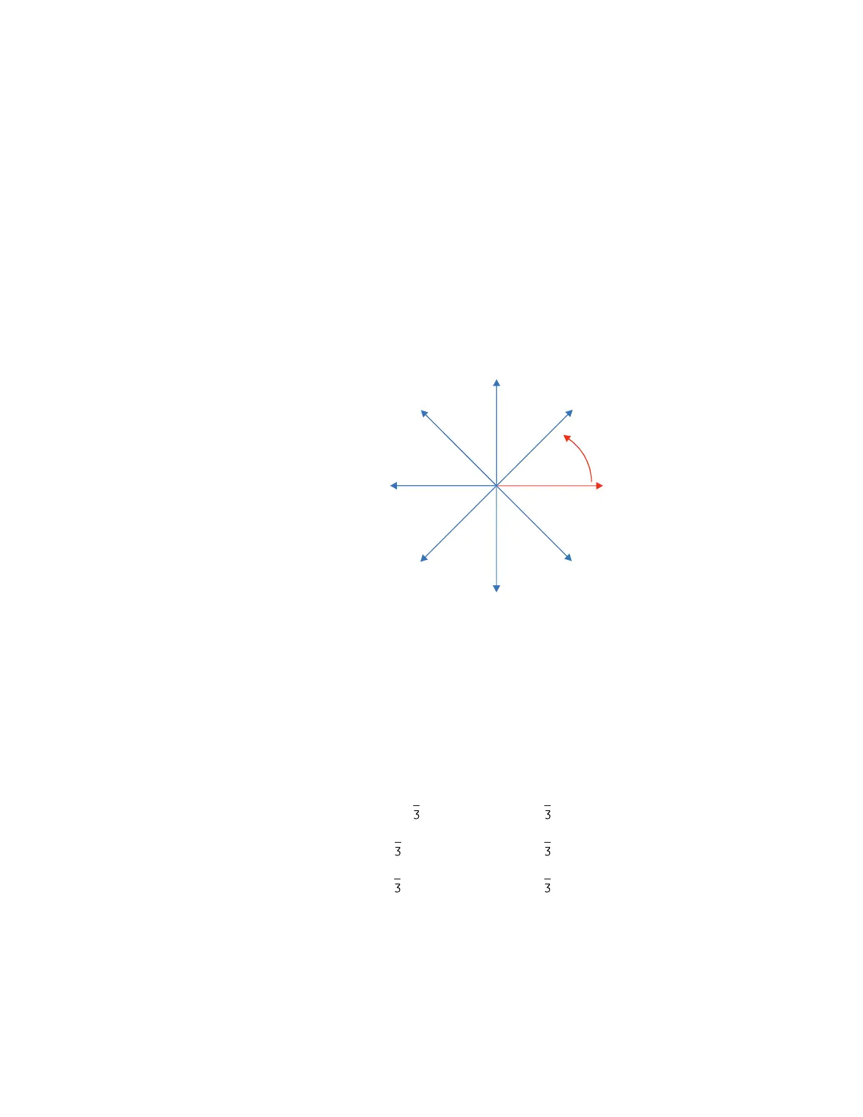
phase angles are not referenced. The phase angles are assigned as positive in the leading
direction and negative in the lagging direction to more closely align with power system
metering conventions. The figure illustrates these.
Figure 492: D90
Plus
phase angle measurement convention
The D90
Plus
calculates voltage symmetrical components for the power system phase A
line-to-neutral voltage, and it calculates symmetrical components of the currents for the
power system phase A current. Owing to the above definition, phase angle relations
between the symmetrical currents and voltages stay the same irrespective of the
connection of instrument transformers. This is important for setting directional protection
elements that use symmetrical voltages.
For display and oscillography purposes, the phase angles of symmetrical components are
referenced to a common value specified by the
Frequency and Phase Reference setting.
The following voltages and currents are measured for wye-connected instrument
transformers in the ABC phase rotation:
Eq. 54
Eq. 55
Eq. 56
$&'5
85 SKDVHDQJOHUHIHUHQFH
3OXV
²
²
²
²
²
²
²
SRVLWLYHDQJOH
GLUHFWLRQ
B,
B9
&%$&*%*$*
,,,999
B,
B9
&%$&*%*$*
,DD,,9DD99
B,
B9
&%$&*%*$*
D,,D,D99D9