CHAPTER 11: METERING METERED VALUES
D90
PLUS
LINE DISTANCE PROTECTION SYSTEM – INSTRUCTION MANUAL 565
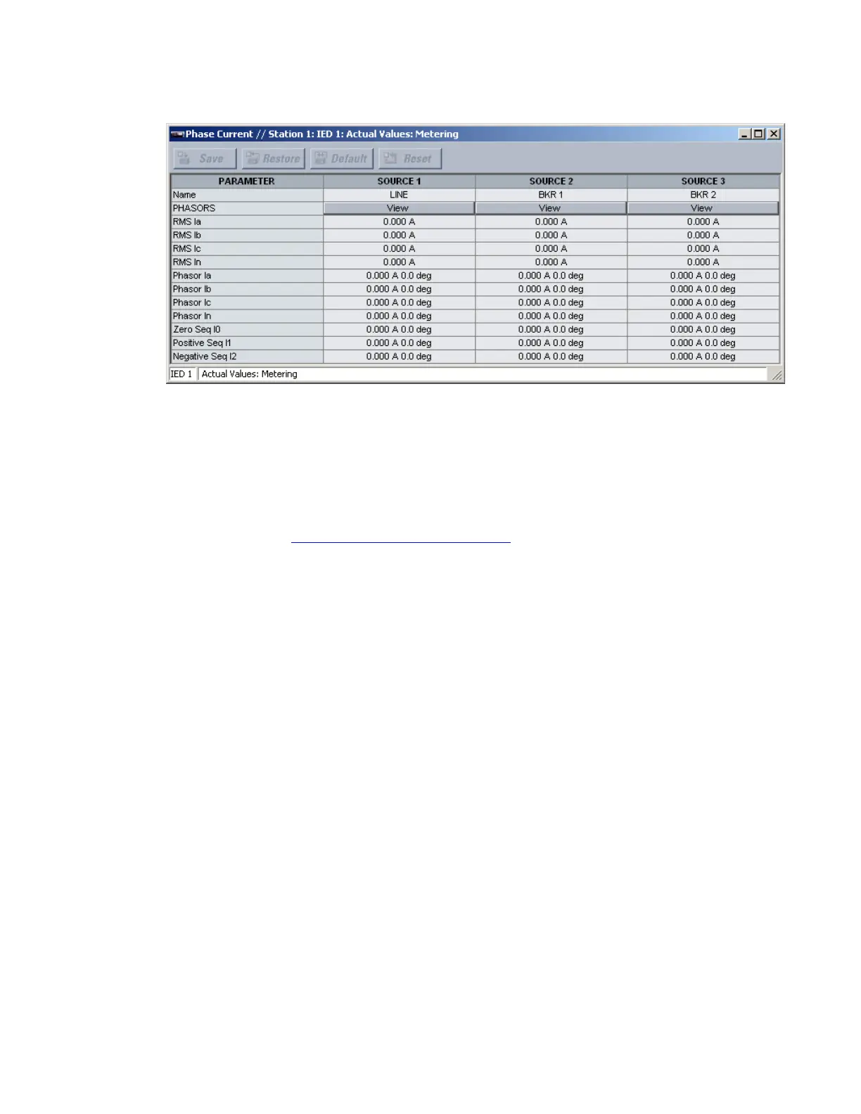
Figure 494: Phase current metering window
The following actual values display for each source.
Name
Range: up to 20 alphanumeric characters
This value displays the user-programmed name for each source.
Phasors
Clicking the View button for this value allows the user to configure and display a
graphical representation of selected current and voltage phasors. For details, see
Observing current and voltage phasors
on page 571.
RMS Ia, RMS Ib, RMS Ic, RMS In
Range: 0 to 999999.999 A in steps of 0.001
These values display the phase A, phase B, phase C, and neutral RMS current on each
source.
Phasor Ia, Phasor Ib, Phasor Ic, Phasor In
Range: 0 to 999999.999 A in steps of 0.001; –359.0° to 0.0° in steps of 0.1°
These values display the magnitude and phase angles for phase A, phase B, phase C,
and neutral current on each source.
Zero Seq I0
Range: 0 to 999999.999 A in steps of 0.001; –359.0° to 0.0° in steps of 0.1°
This value displays the magnitude and phase angle for the zero-sequence current (I_0)
on each source.
Positive Seq I1
Range: 0 to 999999.999 A in steps of 0.001; –359.0° to 0.0° in steps of 0.1°
This value displays the magnitude and phase angle for the positive-sequence current
(I_1) on each source.
Negative Seq I2
Range: 0 to 999999.999 A in steps of 0.001; –359.0° to 0.0° in steps of 0.1°
This value displays the magnitude and phase angle for the negative-sequence current
(I_2) on each source.