CHAPTER 3: INSTALLATION WIRING
D90
PLUS
LINE DISTANCE PROTECTION SYSTEM – INSTRUCTION MANUAL 57
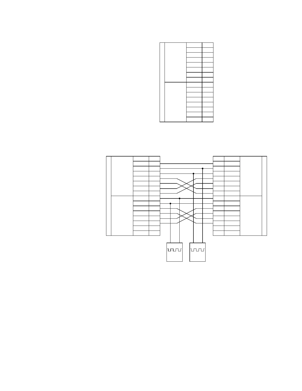
Figure 33: RS422 interface connections
The following figure shows the typical pin interconnection between two dual-channel
RS422 interfaces. All pin interconnections are to be maintained for a connection to a
multiplexer.
Figure 34: Typical connection between two RS422 interfaces
Each channel of the RS422 interface accepts a clock input for transmit timing. It is
important that the rising edge of the 64 kHz transmit timing clock of the multiplexer
interface is sampling the data in the center of the transmit data window. Therefore, it is
important to confirm clock and data transitions to ensure proper system operation. For
example, the following figure shows the positive edge of the Tx clock in the center of the Tx
data bit.
$&'5
%
7[²
6KLHOG
&20
7[
&ORFN²
5[²
&ORFN
5[
56FRPPXQLFDWLRQV
%E
%E
%E
%E
%D
%D
%D
%D
56
FKDQQHO
7[²
7[
&ORFN²
5[²
&ORFN
5[
%E
%E
%E
%E
%D
%D
%D
%D
56
FKDQQHO
6KLHOG
&20
$&'5
%
7[²
6KLHOG
&20
7[
&ORFN²
5[²
&ORFN
5[
56FRPPXQLFDWLRQV
%E
%E
%E
%E
%D
%D
%D
%D
56
FKDQQHO
7[²
7[
&ORFN²
5[²
&ORFN
5[
%E
%E
%E
%E
%D
%D
%D
%D
56
FKDQQHO
%
7[²
6KLHOG
&20
7[
&ORFN²
5[²
&ORFN
5[
56FRPPXQLFDWLRQV
%E
%E
%E
%E
%D
%D
%D
%D
56
FKDQQHO
%E
%E
%E
%E
%D
%D
%D
%D
56
FKDQQHO
6KLHOG
&20
7[²
7[
&ORFN²
5[²
&ORFN
5[
6KLHOG
&20
²
RU
NESV
²
RU
NESV