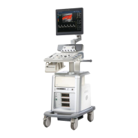
Do you have a question about the GE LOGIQ P6 Series and is the answer not in the manual?
| Brand | GE |
|---|---|
| Model | LOGIQ P6 Series |
| Category | Medical Equipment |
| Language | English |
Provides an overview of the chapter and the service manual, including typical users and models covered.
Describes conventions used in the book, including safety precaution messages and icons.
Outlines crucial safety precautions for operation, service, and repair of the equipment.
Details electromagnetic compatibility, CE compliance, and electrostatic discharge prevention measures.
Provides contact information for technical support and assistance.
Provides information for planning and preparing the installation, including facility and electrical needs.
Details console environmental requirements, power, and electrical specifications.
Outlines purchaser responsibilities and required features for the installation site.
Provides an overview of the installation chapter, including purpose and contents.
Includes average installation time, warnings, and acclimation requirements.
Details procedures for receiving and unpacking the ultrasound system.
Covers verification of customer order, physical inspection, and EMI protection.
Provides steps for powering on, booting up, and shutting down the system.
Details physical dimensions, electrical specifications, and I/O connector panels.
References specifications for probes and intended use, and part numbers.
Guides on configuring system settings, software options, and DICOM connectivity.
Provides a worksheet for documenting site system and TCP/IP settings.
Information for facilitating OnLine Center engineers in connecting to the system.
Provides information on loading the base system software.
Lists warnings related to USB HDD compatibility and starting Echoloader.
Covers documentation requirements, product locator installation, and user manuals.
Provides an overview of the chapter and its purpose related to scanner diagnostics.
Lists the necessary equipment for performing functional checks.
Details general procedures for powering on/booting up and powering off/shutdown.
Describes checks for date, time, location, language, and option settings.
Details checks for peripherals like printers, VCR, and the search/play functions.
Covers validation procedures for the LCD monitor and OSD key assembly.
Details validation procedures for main and sub keyboard assemblies, trackball, and keys.
Covers functional checks for cover parts, air filters, knobs, cup holder, and casters.
Provides procedures for checking various board assemblies like PI128II, DTRX64II, and SYSCONML.
Provides a table for recording site log entries.
Provides an overview of the chapter, system concepts, component arrangement, and PDS.
Explains system architecture with block diagrams for front-end and backend systems.
Details AC power supply functions, including TRANSBOX and APS II power modules.
Describes the keyboard layout, signal I/O, and monitor controls.
Details the I/O interfaces for peripherals on the rear panel.
Illustrates internal cable connections and peripheral cable connections.
Introduces the Service Platform software modules and their functions.
Describes the RFS functionality and system checkout procedures.
Explains the general MRFS functionality and enabling MRFS procedures.
Describes the Fast Polling feature for changing polling rates.
Provides an overview of the chapter on testing and adjusting the scanner.
Ensures compliance with regulatory information and tests required by national law.
Details procedures for adjusting monitor contrast and brightness.
Provides instructions on how to clean the trackball on the keyboard periodically.
Provides an overview of diagnostic tools and software for maintaining image quality.
Details how to capture trouble images and system data for remote diagnostics.
Describes how to capture and record screen settings for presentation or recovery.
Explains the use of the service platform's web-based UI for accessing diagnostic components.
Details capturing and recording screen settings for recovery via OnLine Center.
Explains the diagnostic application interface and how to select tests.
Details utilities like Disruptive Mode and System Shutdown for diagnostics.
Provides descriptions of LEDs for various Assy modules.
Offers troubleshooting flowcharts for common issues like power, boot, and noise problems.
Provides an overview of replacement procedures for modules and subsystems.
Details disassembly and re-assembly procedures for various system components.
Describes the full system software loading process.
Covers installing base image and application software, including verification.
Provides procedures for backing up and restoring system data.
Details procedures for software reloading via Service Platform or remotely.
Provides installation procedures for various mechanical options.
Provides an overview of renewal parts for the LOGIQ™ P6/P6 Pro.
Lists and defines abbreviations used in the manual.
Details monitor components and their part numbers.
Lists keyboard components and their part numbers.
Lists various cover parts and their corresponding part numbers.
Details the components within the NEST assembly and their part numbers.
Lists various body parts and their corresponding part numbers.
Details power supply components like ACPCII Assy and power cords.
Lists various internal and external cables with part numbers.
Lists available system options and their part numbers.
Lists software components and their associated versions.
Lists various probes with part numbers and compatibility information.
Lists supported peripherals like printers, VCRs, and DVD recorders with part numbers.
Provides an overview of care and maintenance, including periodic inspections.
Explains the importance of maintenance, particularly for quality assurance.
Specifies how often care and maintenance tasks should be performed.
Lists standard GE tool kits and special tools, supplies, and equipment.
Covers preliminary checks, system checks, peripheral checks, and cleaning procedures.
Details electrical safety tests, including leakage current and grounding continuity.
Provides troubleshooting steps for high leakage currents in chassis, probes, and peripherals.