EasyManuals Logo

GE LOGIQ P6 Series User Manual

GE LOGIQ P6 Series
484 pages
To Next Page IconTo Next Page
To Previous Page IconTo Previous Page
Page #139 background imageLoading...
Page #139 background image
GE HEALTHCARE
DIRECTION 5394152, Revision 5
LOGIQ™ P6/P6 PRO SERVICE MANUAL
Chapter 5 - Page 5-1
Chapter 5
Components and Functions (Theory)
Section 5-1
Overview
This chapter explains LOGIQ™ P6/P6 Pro’s system concepts, component arrangement, and
subsystem function. It also describes the Power Distribution System (PDS) and probes.
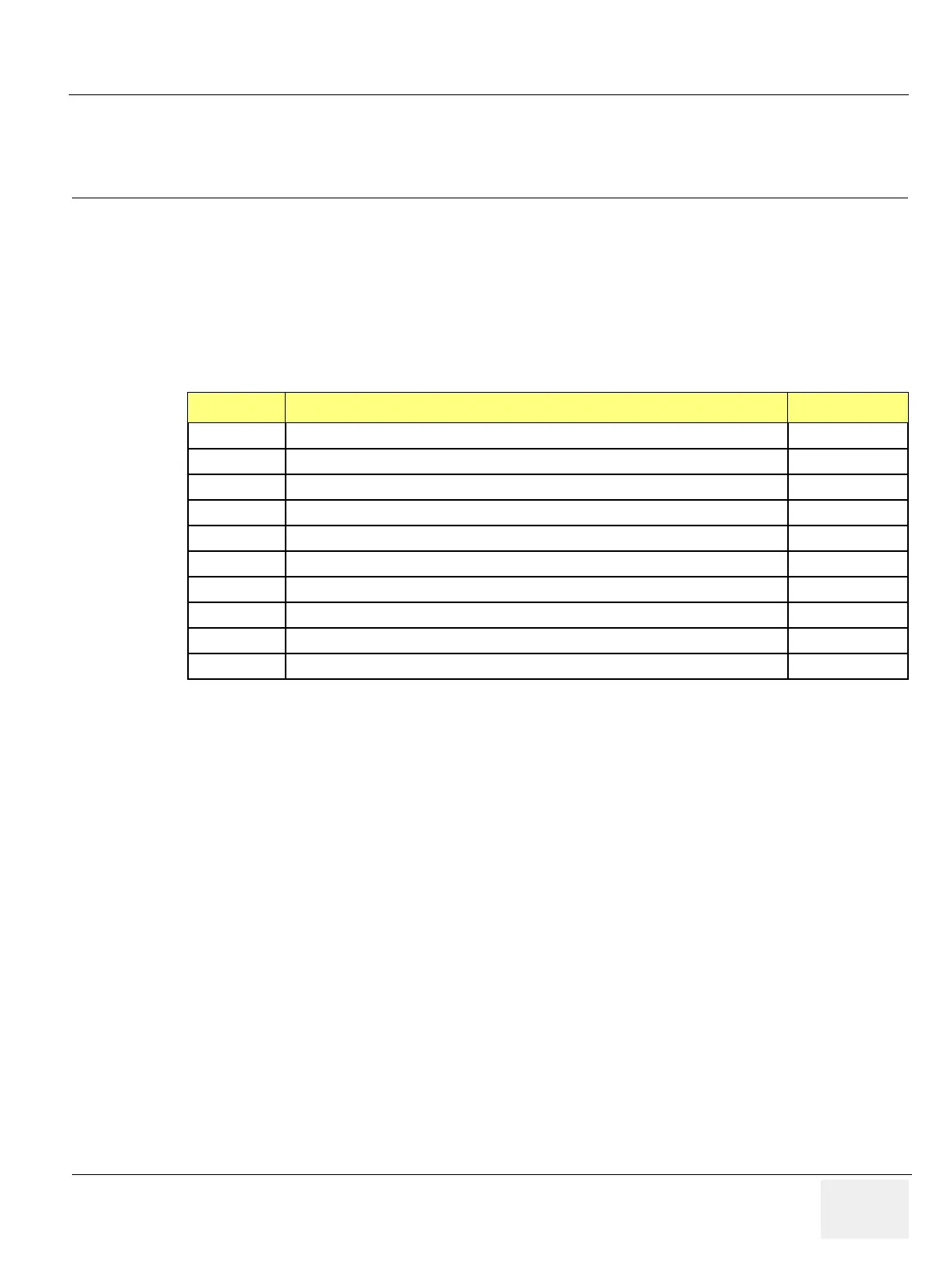
Table 5-1 Contents in Chapter 5
Section Description Page Number
5-1 Overview 5-1
5-2 Block Diagrams and Theory 5-2
5-3 Power Diagrams 5-9
5-4 Top Console 5-13
5-5 P6 ARP II (Rear Panel) 5-17
5-6 Cable Connection 5-19
5-7 Service Platform 5-23
5-8 RFS (Service For Request) 5-35
5-9 Machine RFS 5-40
5-10 Fast Polling 5-42

Table of Contents

Questions and Answers:

Question and Answer IconNeed help?

Do you have a question about the GE LOGIQ P6 Series and is the answer not in the manual?

GE LOGIQ P6 Series Specifications

General IconGeneral
Power Supply100-240 VAC, 50/60 Hz
Imaging ModesB-Mode, M-Mode, Color Doppler, Power Doppler
ApplicationsVascular, Musculoskeletal
Operating Temperature10°C to 40°C
Display15-inch LCD
Relative Humidity20% to 80% (non-condensing)

Related product manuals