EasyManuals Logo

GE LOGIQ P6 Series User Manual

GE LOGIQ P6 Series
484 pages
To Next Page IconTo Next Page
To Previous Page IconTo Previous Page
Page #267 background imageLoading...
Page #267 background image
GE HEALTHCARE
DIRECTION 5394152, Revision 5
LOGIQ™ P6/P6 PRO SERVICE MANUAL
Chapter 8 - Page 8-41
8-2-9 English, Greek, Russian, Swedish, Norwegian A/N Key assy
8-2-9-1 Tools
Common Phillips screwdrivers
8-2-9-2 Preparations
Shut down the system and switch off the main breaker.
8-2-9-3 Removal procedure
1.) Remove the Main Keyboard Assy. Refer to the 8-2-6 "Main Keyboard Assy" on page 8-37.
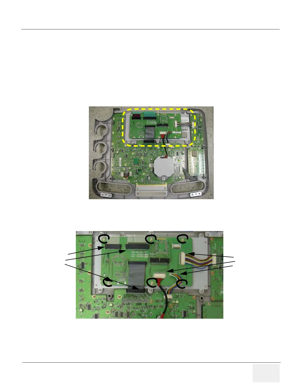
2.) Remove USB PCB by unscrewing 6 screws (1-6) and disconnecting the 6 cables.
Figure 8-76 A/N Key in keyboard
Figure 8-77 USB PCB
Connectors
1 ~ 3
Connector 3
4~ 6

Table of Contents

Questions and Answers:

Question and Answer IconNeed help?

Do you have a question about the GE LOGIQ P6 Series and is the answer not in the manual?

GE LOGIQ P6 Series Specifications

General IconGeneral
Power Supply100-240 VAC, 50/60 Hz
Imaging ModesB-Mode, M-Mode, Color Doppler, Power Doppler
ApplicationsVascular, Musculoskeletal
Operating Temperature10°C to 40°C
Display15-inch LCD
Relative Humidity20% to 80% (non-condensing)

Related product manuals