GE HEALTHCARE
DIRECTION 5394152, Revision 5
LOGIQ™ P6/P6 PRO SERVICE MANUAL
Page 3-18 Section 3-4 - Preparing for Installation
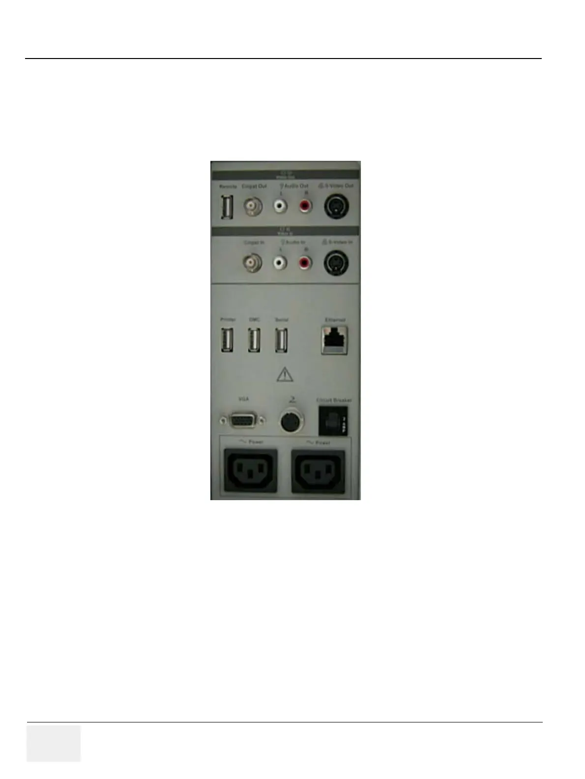
3-6-4 External I/O Connector Panel
Located on the rear panel are video input and output connectors, audio input and output, USB,
footswitch connector power connector and control connections for VCR or DVD Recorder, printer, and
service tools.
This section indicates the pin assignment for each connector.
NOTE: Each outer (case) ground line of peripheral/accessory connectors are protectively grounded.
Signal ground lines are not isolated, except the Service port (3). All of signal lines (include
signal GND) of the Service port are isolated.
Figure 3-14 Rear Connector Panel

 Loading...


